Clock output procedure, Examle of remote control application – NEC PD75402A User Manual
Page 76
65
CHAPTER 5. PERIPHERAL HARDWARE FUNCTIONS
5.3.3
Clock Output Procedure
Clock pulse output is performed by the following procedure.
(i)
Set the clock output mode register.
(ii)
Write 0 to the P22 output latch.
(iii) Set the port 2 input/output mode to output.
This procedure may be reversed depending on the treatment of P22/PCL prior to clock output.
Example
1.
To output a 65.5 kHz (at 4.19 MHz operation) clock from the PCL/P22 pin. (The PCL/P22 pin outputs
the clock from the high-impedance state.)
MOV
A, #1011B
MOV
CLOM, A
; CLOM = 1011B
CLR1
PORT2.2
; P22
←
0
MOV
XA, #04H
MOV
PMGB, XA
; PMGB = 00000100B
2.
To output
Φ
. (The PCL/P22 pin outputs the clock from the low-impedance state.)
MOV
A, #0
OUT
PORT2, A
; P22
←
0
MOV
XA, #04H
MOV
PMGB, XA
MOV
A, #1000B
MOV
CLOM, A
; CLOM
←
1000B
5.3.4
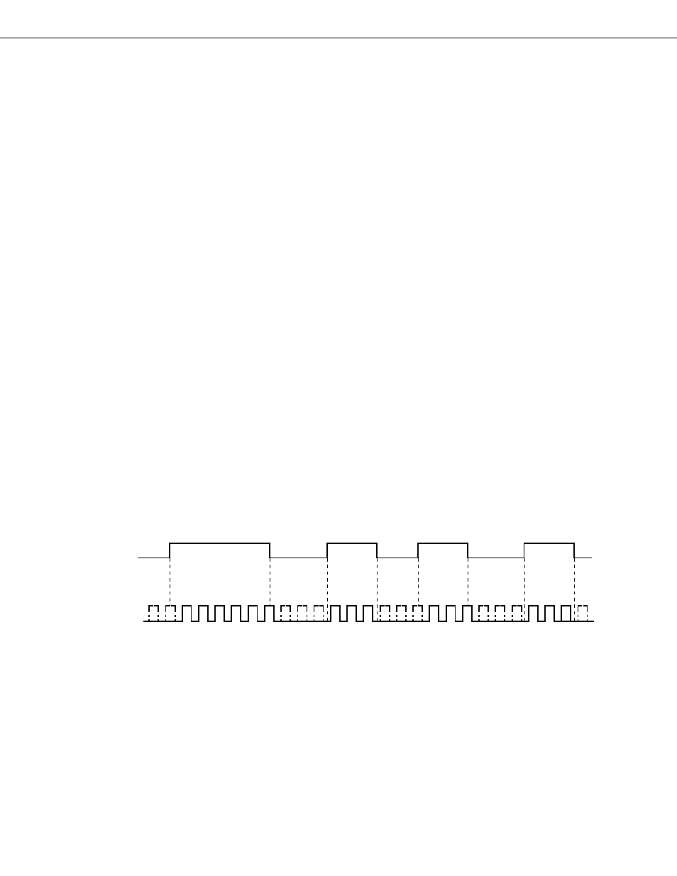
Examle of Remote Control Application
The
µ
PD75402A clock output functions can be used in remote control applications. The remote control output
carrier frequency is selected by the clock frequency selection bits of the clock output mode register. Pulse output
enabling/disabling is performed by software control of the enable/disable bit.
When switching between clock output enabled/disabled states, consideration has been given to ensuring that
a short pulse is not output.
Fig. 5-20 Example of Remote Control Application
CLOM.3
PCL Pin
Output