Normal operating mode, P00 to p03 (port 0), p10, p12 (port 1) – NEC PD75402A User Manual
Page 24
13
CHAPTER 2. PIN FUNCTIONS
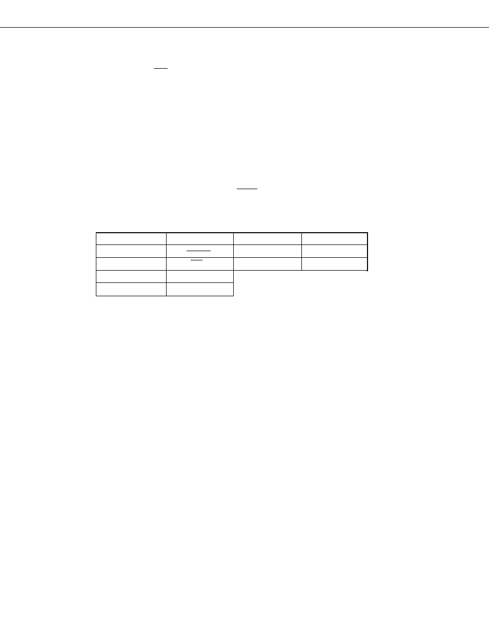
Port 0
Dual-Function
Pin Port 1
Dual-Function Pin
P00
P10
INT0
P01
SCK
P12
INT2
P02
SO/SB0
P03
SI
2.2
NORMAL OPERATING MODE
2.2.1
P00 to P03 (Port 0) ..... SCK, SO/SB0, SI Dual-Function Input
P10, P12 (Port 1) ..... INT0, INT2 Dual-Function Input
P00 to P03 are the 4-bit input port: Port 0’s input pins. P10 and P12 are the 2-bit input port: Port 1’s input pins.
Ports 0 and 1 also have the functions of the various control signal pins shown in Table 2-1 in addition to the
functions as input ports. The status of each of Ports 0 and 1 is always inputtable irrespective of the dual-function
pin operation.
Both Ports 0 and 1 have Schmitt-triggered input to prevent malfunction by noise. P10 is built in with the noise
eliminator by the sampling clock and P12 is built in with the noise eliminator by analog delay.
Ports 0 and 1 allow to designate to build in the pull-up resistor respectively in 3-bit units (P01 to P03) and bit-
wise (P12 only). Such designation is made using the pull-up resistor designation register (POGA). Neither P00 or
P10 can be built in with the pull-up resistor.
Any of these pins assumes the input port mode at RESET input.
Table 2-3 Port 0’s, 1’s Dual-Function Pins