NEC PD75402A User Manual
Page 100
89
CHAPTER 5. PERIPHERAL HARDWARE FUNCTIONS
(3)
Serial clock selection
Serial clock selection is performed by setting bit 1 of the serial operating mode register (CSIM). Either of the
following clocks can be selected.
Table 5-6 Serial Clock Selection and Use (in 3-Wire Serial I/O Mode)
Serial Clock
CSIM 1
Source
Serial Clock
Masking
Possible Timing for Shift
Register R/W and Serial
Transfer Start
External
SCK
0
Automatically
masked at end of
8-bit data
transfer.
Possible only when serial transfer
is halted* or when SCK is high.
Use
Slave CPU
f
XX
/2
4
1
Possible only when serial transfer
is halted* or when SCK is high.
Medium-speed
serial transfer
Mode
Register
*
“When serial transfer is halted” means in the operation-halted mode, or when the serial clock is masked after
an 8-bit transfer.
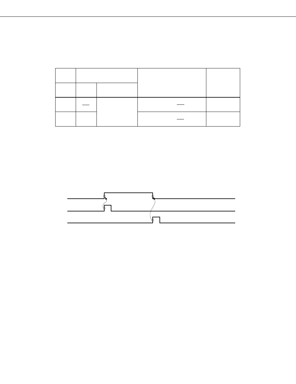
(4)
Signals
RELT and CMDT operation is shown in Fig. 5-30.
Fig. 5-30 RELT & CMDT Operation
SO
RELT
CMDT