NEC PD75402A User Manual
Page 130
119
CHAPTER 5. PERIPHERAL HARDWARE FUNCTIONS
V
DD
SB0 (SB1)
SCK
SB0 (SB1)
SCK
SB0
SCK
SB0 (SB1)
SCK
(12) SBI mode application
This section presents examples of applications in which serial data communication is performed in SBI mode.
In these application examples, the
µ
PD75402A is operated as a slave CPU on the serial bus.
Also, the master can be changed by a command.
(a)
Serial bus configuration
In the serial bus configuration in the application examples given here, the
µ
PD75402A is connected to the
bus line as one of the devices on the serial bus.
The
µ
PD75402A uses two pins: The serial data bus SB0 (P02/SO), and the serial clock SCK (P01).
An example of the serial bus configuration is shown in Fig. 5-53. Only addresses C0H through C7H can be
allocated to the
µ
PD75402A.
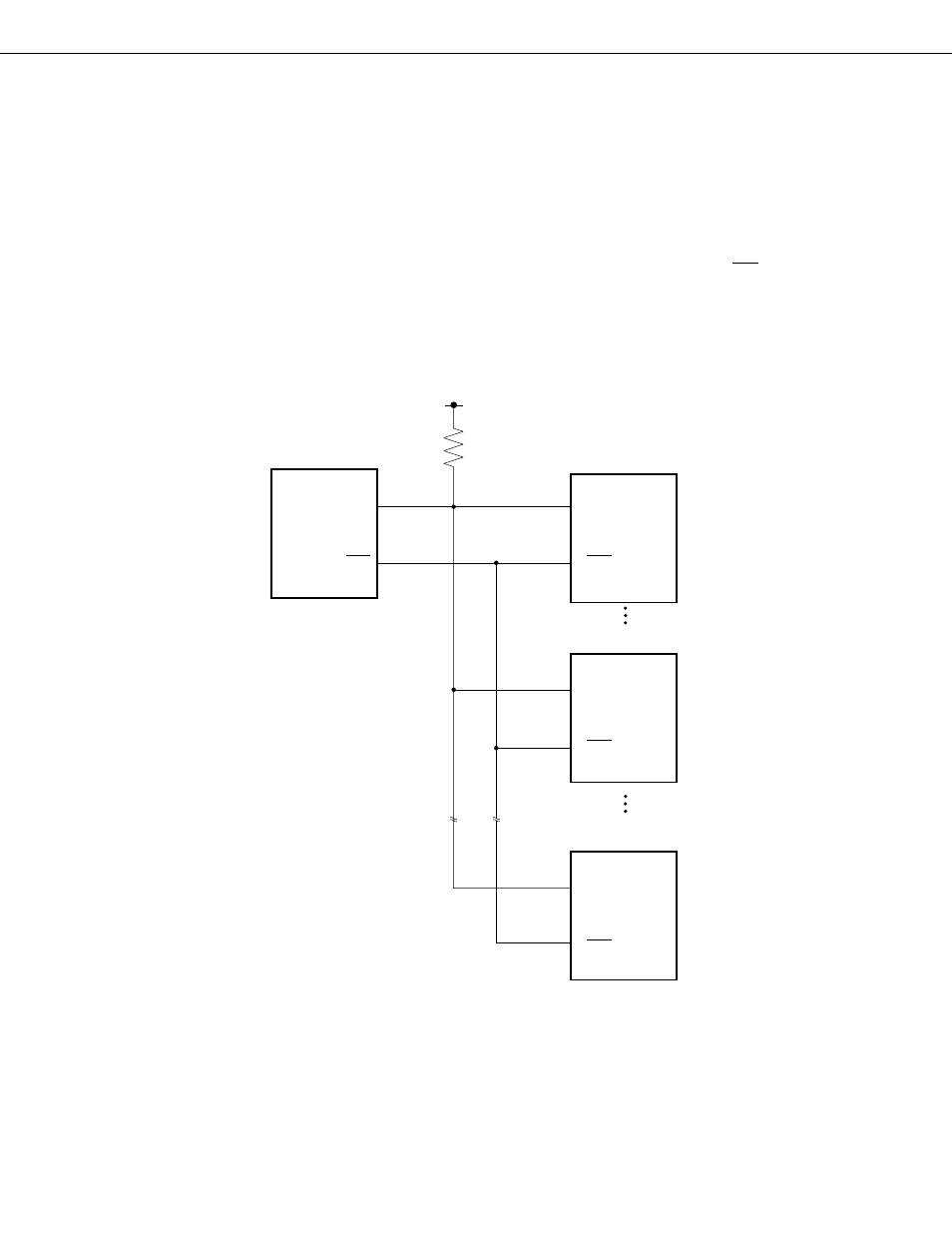
Fig. 5-53 Example of Serial Bus Configuration
Master CPU
µ
PD75308
Slave CPU
µ
PD75328
Address C0H
Address 1
Address N
Slave IC
Slave CPU
µ
PD75402A