Outline of functions – NEC PD75402A User Manual
Page 13
2
CHAPTER 1. GENERAL
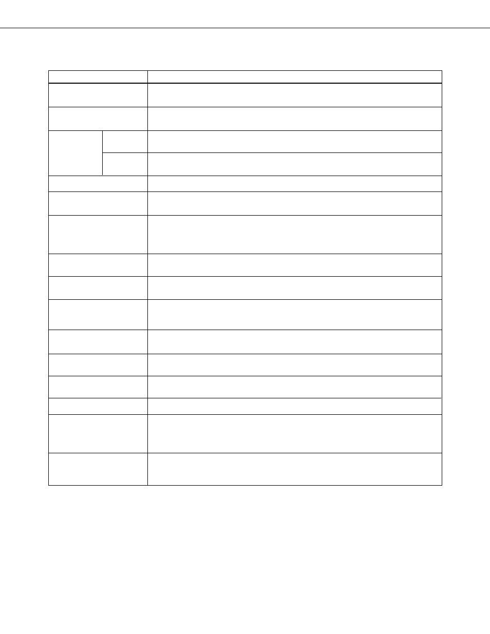
Item
Description
1.1
OUTLINE OF FUNCTIONS
Number of basic
instructions
Instruction
execution time
Built-in
memory
General register
Accumulators
I/O line
Pull-up resistor
Clock output
Timer/Counter
Serial interface
Vectored
interrupt
Test input
Standby
Instruction set
Package
37
• 0.95
µ
s, 1.91
µ
s, 15.3
µ
s (at 4.19 MHz operation)
selectable between 3 levels
1920
×
8 bits (
µ
PD75402A: Mask ROM,
µ
PD75P402: One-time PROM)
64
×
4 bits (RAM)
4 bits
×
4, or 8 bits
×
2 (memory mapping)
3 accumulators to suit manipulation data length
• Bit accumulator (CY), 4-bit accumulator (A), 8-bit accumulator (XA)
Total 22 lines
• CMOS input port
: 6 lines
• CMOS input/output port (LED direct drivable 8 lines)
: 12 lines
• N-ch open-drain input/ output port (LED direct drivable)
: 4 lines
• Pull-up resistor built-in control possible by software
: 16 lines
• Pull-up resistor built-in control possible by mask option (
µ
PD75402A only)
: 4 lines
• 1.05 MHz, 524 kHz, 65.5 kHz (at 4.19 MHz operation)
• Applicable to remote control output
8-bit basic interval timer
• Reference time generation (1.95 ms, 31.3 ms : at 4.19 MHz operation)
• Watchdog timer applicable
• 8 bits
• 2 transfer modes (clock synchronous 3-wire system mode/SBI mode)
External: 1 line, internal : 2 lines
External: 1 line
(For details, see CHAPTER 6 “INTERRUPT FUNCTIONS”.)
STOP mode/HALT mode
• Bit manipulation instruction (set, clear, test, Boolean operation)
• 1-byte relative branch instruction
• 4-bit operation instruction (add, Boolean operation, compare)
• 4, 8-bit data transfer instruction
• 28-pin plastic DIP (600 mil)
• 28-pin plastic shrink DIP (400 mil)
• 44-pin plastic QFP (
■
■
10 mm)
Program
memory
Data
memory