NEC PD75402A User Manual
Page 90
79
CHAPTER 5. PERIPHERAL HARDWARE FUNCTIONS
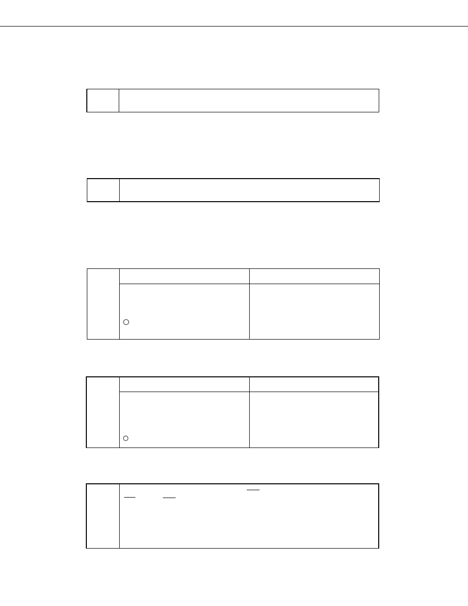
Fig. 5-26 Serial Bus Interface Control Register (SBIC) Format (2/3)
Bus release trigger bit (W)
RELT
The bus release signal (REL) trigger output control bit. The SO latch is set (1) by setting this
bit (RELT = 1), after which the RELT bit is automatically cleared (0).
Note
SB0 must not be cleared during a serial transfer: Ensure that it is cleared before a transfer is started or after
it is completed.
Command trigger bit (W)
CMDT
The command signal (CMD) trigger output control bit. The SO latch is cleared (0) by setting
this bit (CMDT = 1), after which the CMDT bit is automatically cleared (0).
Note
SB0 must not be cleared during a serial transfer: Ensure that it is cleared before a transfer is started or after
it is completed.
Bus release detection flag (R)
Clearing Conditions (RELD = 0)
Setting Condition (RELD = 1)
➀
When a transfer start instruction is
executed
➁
When RESET is input
➂
When CSIE = 0 (See Fig. 5-25)
When SVA and SIO do not match
when an address is received
RELD
When the bus release signal (REL) is de-
tected
Command detection flag (R)
Clearing Conditions (CMDD = 0)
Setting Condition (CMDD = 1)
➀
When a transfer start instruction is
executed
➁
When tje bus release signal (REL) is
detected
➂
When RESET is input
When CSIE = 0 (See Fig. 5-25)
CMDD
When the command signal (CMD) is de-
tected
Acknowledge trigger bit (W)
When ACKT is set after the end of a transfer, ACK is output in synchronization with the next
SCK. After th ACK signal is output, ACKT is automatically cleared (0).
Note 1. ACKT must not be set (1) before completion of a serial tramsfer or during a
transfer.
2. ACKT cannot be clearedby software.
3. When ACKT is set, ACKE should be reset to 0.
ACKT
4
4