NEC PD75402A User Manual
Page 116
105
CHAPTER 5. PERIPHERAL HARDWARE FUNCTIONS
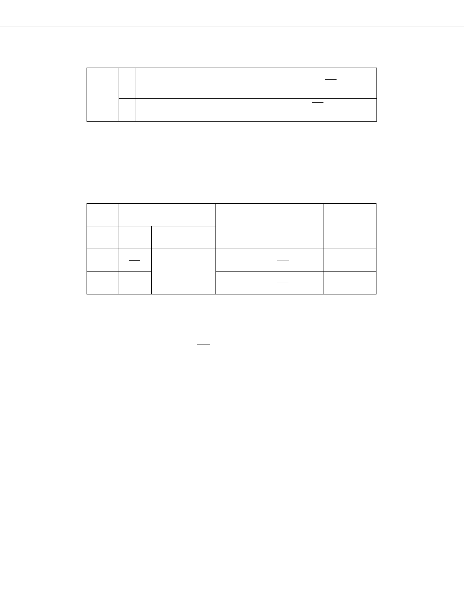
Busy enable bit (R/W)
0
➀
Disablin of automatic busy signal output
➁
Busy signal output is stopped in synchronization with the fall of SCK immediately
after execution ofthe clearing instruction.
The busy signal is output in synchronization with the fall or SCK following the
acknowledge signal.
1
BSYE
(4)
Serial clock selection
Serial clock selection is performed by setting bit 1 of the serial operating mode register (CSIM). Either of the
following clocks can be selected.
Table 5-7 Serial Clock Selection and Use (in SBI Mode)
*
“When serial transfer is halted” means in the operation- halted mode, or when the serial clock is masked after
an 8-bit transfer.
When the internal system clock is selected SCK stops at 8 pulses internally, but externally the count continues
until the slave is in the ready state.
Serial Clock
CSIM 1
Source
Serial Clock
Masking
Possible Timing for Shift
Register R/W and Serial
Transfer Start
External
SCK
0
Automatically
masked at end of
8-bit data
transfer.
Possible only when serial transfer
is halted* or when SCK is high.
Use
Slave CPU
f
XX
/2
4
1
Possible only when serial transfer
is halted* or when SCK is high.
Medium-speed
serial transfer
Mode
Register