NEC PD75402A User Manual
Page 143
132
CHAPTER 6. INTERRUPT FUNCTIONS
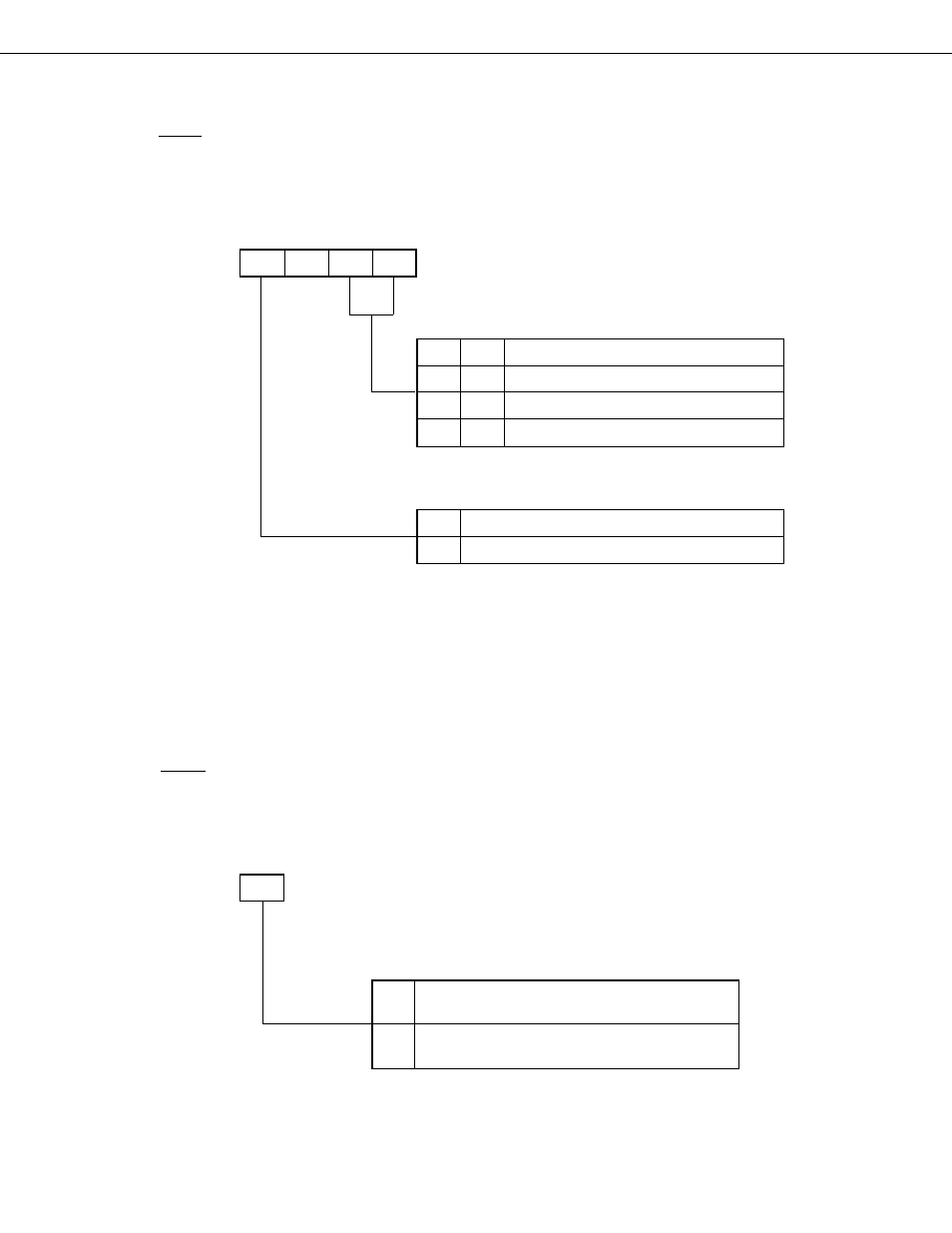
The format of the edge detection mode register (IM0) which is used to select the detected edge is shown in Fig.
6-6. IM0 is set by 4-bit memory handling instructions.
On an RESET input, all bits of IM0 are cleared to 0 and the rising edge is specified for INT0.
Fig. 6-6 Edge Detection Mode Register Format
Note
As the interrupt request flag may be set when the edge detection mode register is modified, the following
procedure should be used: Disable interrupts and modify the mode register in advance, clear the interrupt
request flag with the CLR1 instruction, and then enable interrupts again. Also, when f
X
/64 is selected as
the sampling clock by modifying IM0, the interrupt request flag must be cleared after the elapse of 16
machine cycles following the mode register modification.
(3)
Interrupt master enable flag (IME)
The interrupt master enable flag specifies acknowledgment enabled/disabled for all interrupts.
IME is manipulated by the EI/DI instructions.
With a RESET input, IME is cleared to 0 and acknowledgment of all interrupts is disabled.
Fig. 6-7 IME Format
Interrupt master enable flag (IME)
3
FB2H
IME
0
1
All interrupts are disabled, vectored interrupts
are notinitiated.
Interrupt enabling/disabling is controlled by the
corresponding interrupt enable flag.
3
2
1
0
Symbol
FB4H
IM03
0
IM01
IM00
IM0
0
0
Rising edge specification
0
1
Falling edge specification
1
0
Rising and falling edge specification
1
1
Ignored (interrupt request flag is not set)
Detected edge specification
Sampling clock specification
Address
0
Φ
(0.95
µ
s/1.91
µ
s/15.3
µ
s: operating at 4.19 MHz)
1
f
x
/64 (15.3
µ
s: Operating at 4.19 MHz)
Address