NEC PD75402A User Manual
Page 163
152
CHAPTER 9. INSTRUCTION SET
(3)
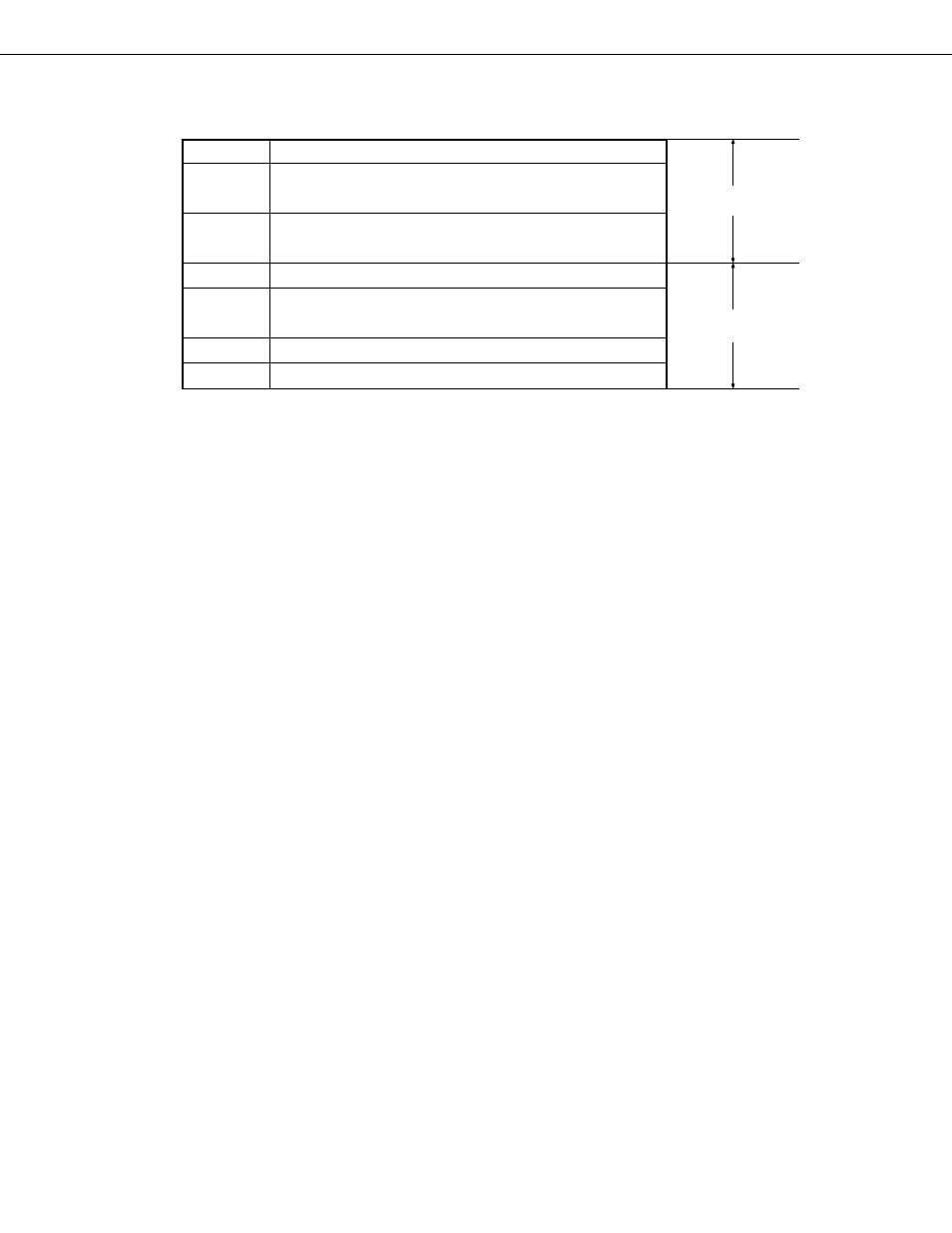
Description of addressing area field symbols
*
1
MB = 0
*
2
MB = 0 (00H to 3FH)
MB = 15 (80H to FFH)
*
3
MB = 15, fmem = FB0H to FBFH,
FF0H to FFFH
*
4
addr = 000H to 77FH
*
5
addr = (Current PC) – 15 to (Current PC) – 1,
(Current PC) + 16 to (Current PC) + 2
*
6
caddr = 000H to 77FH
*
7
faddr = 000H to 77FH
Remarks
1.
MB is the accessible memory bank.
2.
*4 to *7 are the addressable areas.
(4)
Description of machine cycle field
S is the number of machine cycles required when the skip operation is performed by an instruction with skip.
The value of S changes as follows:
• Do not skip next instruction ..... S = 0
• Skip next instruction ................. S = 1
One machine cycle equals one cycle of CPU clock
Φ
. Three times can be selected by PCC setting. (See section
5.2.2(1).)
Data memory
addressing
Program memory
addressing