Konica Minolta Magicolor 5440 DL User Manual
Page 192
Main Unit Field Service
Jam Display
4-5
IV
T
roub
lshoo
t
in
g
1.5.2
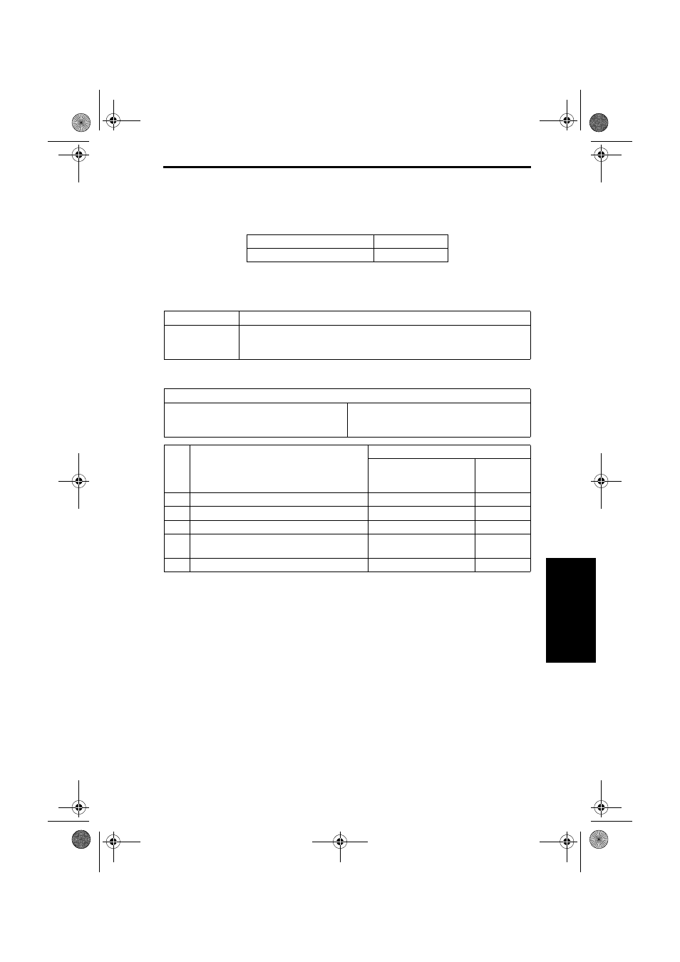
Misfeed at Tray 1 media feed section (Misfeed at Tray 2 media feed section)
NOTE
• Make sure to note that the feed trays are named differently, depending on the
printer model.
• The following procedures use the name for magicolor 5430 DL/5440 DL.
A. Detection Timing
B. Action
magicolor 5430 DL / 5440 DL
magicolor 5450
TRAY 1
TRAY 2
Type
Description
Detection of
misfeed at Tray 1
media feed section
The media does not unblock the Synchronizing Roller Sensor (PC4) even after
the lapse of a given period of time after the media feed sequence has been
started.
Relevant Electrical Parts
Synchronizing Roller Sensor (PC4)
Tray 1 Paper Feed Clutch (CL1)
Intermediate Transport Motor (M3)
Mechanical Control Board (PWB-A)
Step
Action
WIRING DIAGRAM
Control Signal
Location
(Electrical
Component)
1
Initial check items
-
-
2
PC4 sensor check
PWB-A PJ15A-3 (ON)
2-H
3
CL1 operation check
PWB-A PJ6A-2 (ON)
2-K
4
M3 operation check
PWB-A PJ27A-8 (LOCK)
PWB-A PJ27A-5 (REM)
2-I
5
Change PWB-A.
-
-
5450_E.book_PDF.book 5 ページ 2005年4月12日 火曜日 午後12時54分