1 specifying delay time for i·c, Specifying delay time for i²c, Table 19.2 – Siemens AC75 User Manual
Page 498: Values for calculating the delay, Figure 19.1, Formula for calculating the delay, Figure 19.2, Delay time on i²c after write, Specifying delay time for, 1 specifying delay time for i²c
AC75 AT Command Set
19.8 AT^SSPI
s
AC75_ATC_V01.002
Page 498 of 569
10/30/06
Confidential / Released
19.8.1
Specifying Delay Time for I²C
The following figures are provided to assist you in specifying appropriate values for the parameters
and
. All delays are relative to the data transfer rate. To calculate the delay use the formula and the
values given below.
Table 19.2: Values for calculating the delay
Subparameter
Bit
Hexadecimal
Selected function
SPI mode
D15 - D12
0
1
2
3
Four different SPI modes. Phase and
polarity of all SPI modes are illustrated in
Section
.
Chip Select (CS) mode
D11 - D8
0
One Chip Select per Transfer Frame.
Arrangement of bytes
D7 - D4
0
Big endian
Bit sequence
(arrangement of bits on the SPI)
D3 - D0
0
MSB first
Figure 19.1: Formula for calculating the delay
Parameter
Values
Delay value
Master clock
13 MHz
Default data transfer rate
400 bps
User data transfer rate
Value selected with subparameter data transfer rate within
, for example 100 kbps or 400 kbps
Delay_min for Write
7.4 µs at 100 kbps
2.0 µs at 400 kbps
Delay_min for Read
9.9 µs at 100 kbps
2.6 µs at 400 kbps
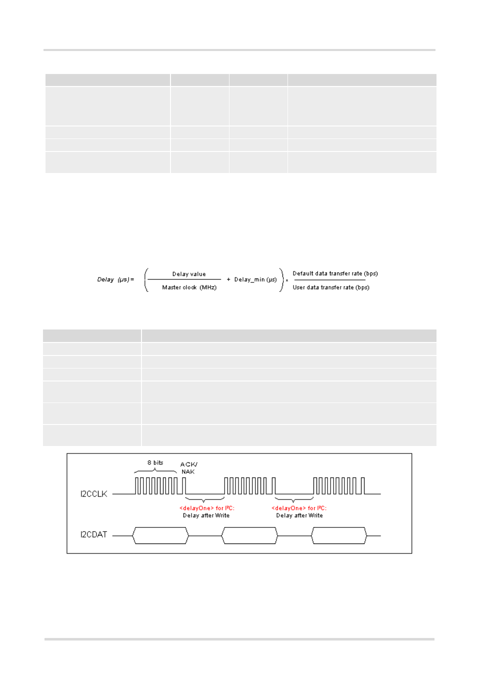
Figure 19.2: Delay time on I²C after Write