Yaskawa GPD503 Drive User Manual
Page 88
2.33 V/f PATTERN - CUSTOM Continued
Initial Voltage Values *
When Sn-02 = 01 When Sn-02 = 0F
B.
Cn-02: Frequency – Max. (Fmax)
Cn-03: Voltage – Max. (Vmax)
. . . . . . . . . . . . .
230.0
V
200.0
V
Cn-04: Frequency – Max. Voltage point (F
A
)
Cn-05: Frequency – Midpoint (F
B
)
Cn-06: Voltage – Midpoint (V
C
)
. . . . . . . . . . . . .
17.2
V
15.0
V
Cn-07: Frequency – Min. (Fmin)
Cn-08: Voltage – Min. (Vmin)
. . . . . . . . . . . . .
11.5
V
10.0
V
* Double indicated values for 460V units;
2.5 times indicated values for 575V units.
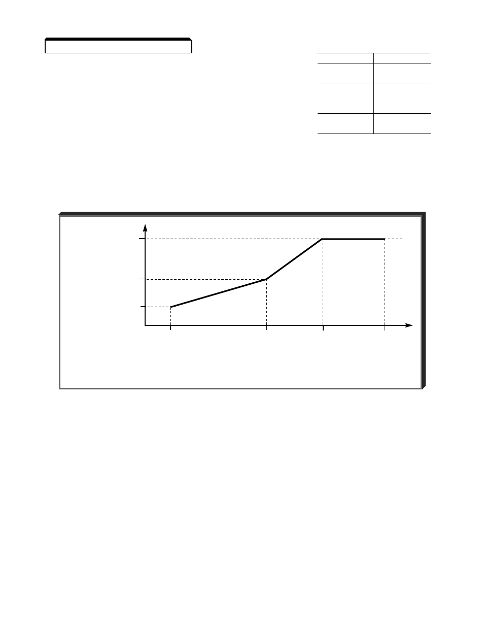
These seven control constants define the custom V/f pattern, only if Sn-02 is set to
0F
.
The illustration below shows how these constants relate to each other in establishing the
custom V/f pattern.
2-49
NOTE: To establish a V/f pattern with a straight line from Fmin to F
A
, set
F
B
= Fmin. The setting of V
C
is then disregarded and does not affect the
V/f pattern.
IMPORTANT
The constant settings are checked whenever power is applied to
the GPD 503, or each time the DATA/ENTER key is pressed while in
the Program (PRGM) mode. A constant set value failure (
oPE
) will
occur if any part of the following relationships among Cn-02 thru
Cn-08 is not TRUE:
(a)
Fmax
* F
A
* F
B
* Fmin
(b)
Vmax > V
C
* Vmin
V/f Characteristics Set by Cn-02 thru Cn-08
Vmax
(03)
OUTPUT
VOLTAGE
V
C
(06)
Vmin
(08)
Fmin
F
B
F
A
Fmax
(07)
(05)
(04)
(02)
OUTPUT FREQUENCY
[ Parenthesized values indicate control constant numbers. ]