Yaskawa GPD503 Drive User Manual
Page 101
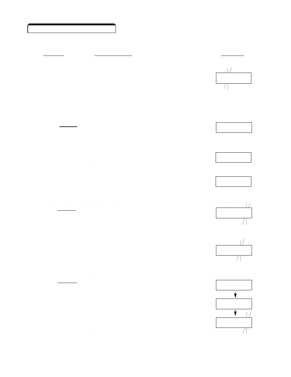
C. Drive Operation (2-Wire Control) By External Input Signals:
ACTION
DESCRIPTION
DISPLAY
Apply Power
DRIVE lamp is on.
The Frequency Reference (An-01) set
value appears.
NOTE: If the GPD 503 has already been
programmed for operation by external signal
input, frequency display will be as shown at
“...Return to Drive Mode” action on next page;
then continue at “Set Auto/Manual...” action.
Press PRGM Key
DRIVE lamp turns off. First Frequency
DRIVE
Reference Memory Settings constant
to Select Program
number is displayed.
Mode
Press DSPL Key
First System Constants number is
Twice
displayed.
Use
^
and
Value of Sn-XX digits scrolls up or down
v
Keys as
by 1 each time one of these keys is
Necessary pressed.
Until Display
Shows
Sn-04
Press DATA
The value currently stored in memory
ENTER
for the constant is displayed.
Key to Display
NOTE: Factory setting for Sn-04 is 0011 ,
Current Setting
selecting An-01 as frequency reference, and
Jog, Run and Stop by Digital Operator
Press
>
,
^
Blinking position of display shifts to the
and
v
Keys
left. Value of blinking digit increases
as Necessary
or decreases when keys are pressed.
Until Display
Shows 0000
Press DATA Key
Display lights steady for a short time,
ENTER
then
End
is displayed for approx. 1 sec.
To Write New
Then setting is displayed again, with one
Setting of Sn-04
digit blinking.
Into Memory
NOTE: With Sn-04 set to 0000, frequency
reference is by external signal input, and Jog,
Run and Stop are by external command inputs.
(Sequence continues on next page)
F 0 0.0 0
A n - 0 1
S n - 0 1
S n - 0 4
0 0 1 1
0 0 0 0
0 0 0 0
0 0 0 0
E n d
3-9
3.5 DRIVE MODE OPERATION Continued