4 electrical installation, 1 main circuit input/output, Caution – Yaskawa GPD503 Drive User Manual
Page 14
1.4 ELECTRICAL INSTALLATION
All basic interconnections (using the Digital Operator) are shown in Figures 1-3
through 1-6.
1.4.1 Main Circuit Input/Output
Complete wiring interconnections for the main circuit according to Tables 1-1 and 1-2,
while observing the following:
CAUTION
Use only factory supplied instructions to install dynamic braking
resistors. Failure to do so may cause equipment damage or
personal injury.
• Use 600 V vinyl-sheathed wire or equivalent. Wire size should be determined
considering voltage drop of leads.
• NEVER connect AC main power to output terminals T1 ( U ), T2 ( V ), and T3 ( W ).
• NEVER allow wire leads to contact the GPD 503 enclosure. Short-circuit may result.
• NEVER connect power factor correction capacitors or noise filter to GPD 503 output.
• SIZE OF WIRE MUST BE SUITABLE FOR CLASS I CIRCUITS.
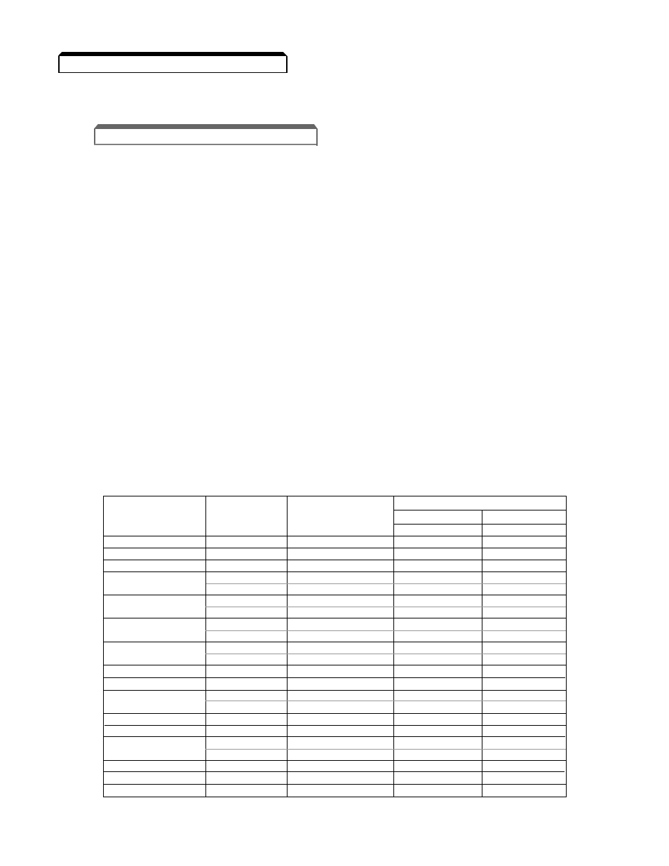
• Use UL listed closed loop connectors or CSA certified ring connectors sized for the
selected wire gauge. The connectors are to be installed using the correct crimp tool
recommended by the connector manufacturer.
WIRE SIZE
TERMINAL
CLOSED-LOOP
CLAMPING TORQUE
AWG
mm
2
SCREW
CONNECTOR
STEEL
COPPER
lb-in
N-m
lb-in
N-m
20
0.5
M3.5
1.25 - 3.5
7.8
0.9
7.0
0.8
18
0.75
M4
1.25 - 4
13.0
1.5
10.4
1.2
16
1.25
M4
1.25 - 4
13.0
1.5
10.4
1.2
M4
2 - 4
13.0
1.5
10.4
1.2
14
2
M5
2 - 5
26.1
20.9
3.1
2.4
M4
3.5 - 4
13.0
1.5
10.4
1.2
12
3.5
M5
3.5 - 5
26.1
20.9
3.1
2.4
M4
5.5 - 4
13.0
1.5
10.4
1.2
10
5.5
M5
5.5 - 5
26.1
20.9
3.1
2.4
M5
8 - 5
26.1
20.9
3.1
2.4
8
8
M6
8 - 6
40.9
34.8
4.8
4.1
6
14
M6
14 - 6
40.9
34.8
4.8
4.1
4
22
M8
22 - 8
100.0
82.6
11.7
10.7
M8
38 - 8
100.0
82.6
11.7
10.7
2
38
M10
38 - 10
182.6
156.5
21.4
18.4
1/0
60
M10
60 - 10
182.6
156.5
21.4
18.4
3/0
80
M10
80 - 10
182.6
156.5
21.4
18.4
M10
100 - 10
182.6
156.5
21.4
18.4
4/0
100
M12
100 - 12
313.0
191.3
36.7
23.1
MCM300
150
M12
150 - 12
313.0
191.3
36.7
23.1
MCM400
200
M12
200 - 12
313.0
191.3
36.7
23.1
MCM650
325
M12
325 - 12
313.0
191.3
36.7
23.1
1-2