Yaskawa GPD503 Drive User Manual
Page 47
2.12 EXTERNAL FAULT INPUTS Continued
B. Sn-15 thru Sn-18: Multi-function
Data
20 - 2F
: External Fault 1 (terminal 5)
Inputs (Term. 5 thru 8)
Data
30 - 3F
: External Fault 2 (terminal 6)
Data
40 - 4F
: External Fault 3 (terminal 7)
Data
50 - 5F
: External Fault 4 (terminal 8)
The multi-function input terminals can be used to monitor external fault contacts. When
the External Fault 1-4 signals are inputted,
E F5
to
E F8
are displayed on the Digital
Operator (steady for a major fault situation, blinking for a minor fault situation). The
second digit of the Sn-15 thru Sn-18 setting is entered as a hexadecimal value; when
converted to its binary equivalent, it defines what type of external fault contact is used and
how the GPD 503 will react to the fault input.
Binary — 0 0 0 0
0 = N.O. contact
1 = N.C. contact
0 = always detected
1 = during operation
00 = ramp to stop
01 = coast to stop
10 = emergency stop
11 = continue operation
(minor fault)
EXAMPLE:
To program External Fault 1 (terminal 5)
for a N.C. contact, always detected, and
GPD 503 to continue operation, solve
for X:
Sn-15 data =
2 X
X = 1 1 0 1
N.C. contact
always detected
continue operation
= 1 1 0 1 (binary) = D (hex)
Sn-15 data =
2d
For the same type of input at External Fault 2 (terminal 6):
Sn-16 data =
3 d
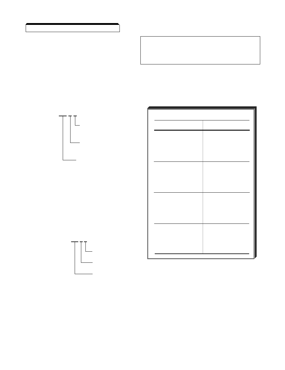
BINARY TO HEX CONVERSION
BINARY
HEX
0 0 0 0
0
0 0 0 1
1
0 0 1 0
2
0 0 1 1
3
0 1 0 0
4
0 1 0 1
5
0 1 1 0
6
0 1 1 1
7
1 0 0 0
8
1 0 0 1
9
1 0 1 0
A
1 0 1 1
B *
1 1 0 0
C
1 1 0 1
D **
1 1 1 0
E
1 1 1 1
F
2-16
*
Appears as "
b
" on Digital Operator.
**
Appears as "
d
" on Digital Operator.