4 auxiliary input and output power option devices, Magnetek drive – Yaskawa GPD503 Drive User Manual
Page 23
1.4 ELECTRICAL INSTALLATION Continued
1.4.4 Auxiliary Input and Output Power Option Devices
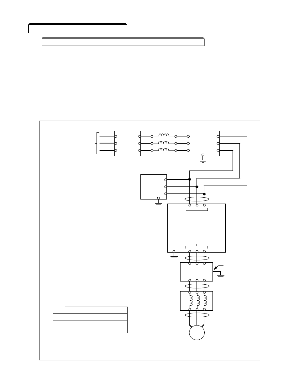
Figure 1-2 is a factory guideline for proper wiring practices and relative locations within
the electrical path from the line to the load. It does not imply what devices are needed for
a particular application, nor does it show what devices were shipped with a particular
order. Therefore, disregard those items in the diagram which are not being used in your
installation.
Mount all power option devices as close to the drive, and keep electrical connections as
short as possible.
DO NOT run input and output wiring in the same conduit.
ISOLATION
TRANSFORMER
INPUT
REACTOR
INPUT
RFI FILTER
L3
L2
L1
H3
H2
H1
X3
X2
X1
C1
B1
A1
C2
B2
A2
C1(L3)
B1(L2)
A1(L1)
(L3)C2
(L2)B2
(L1)A2
L
I
N
E
L
O
A
D
CUSTOMER'S
3Ø A.C. LINE
POWER
SUPPLY
EARTH GROUND
SEE NOTE 2
(G)
RF NOISE
FILTER
SEE NOTE 5
SEE NOTE 3
L3
L2
L1
T3
T2
T1
INPUT
OUTPUT
MagneTek Drive
GND
EARTH GROUND
SEE NOTE 1
SEE NOTES 3, 4
OUTPUT
REACTOR
OUTPUT
RFI FILTER
TO CASE
EARTH
GROUND
SEE NOTE 2
SEE NOTES 3, 4
SEE NOTES 3, 4
A.C. MOTOR
1
2
3
4
5
6
IN
OUT
T3
T2
T1
C1
B1
A1
C2
B2
A2
EARTH GROUND
SEE NOTE 2
SEE NOTE 6
Figure 1-2. Customer Connection Diagram For Isolation Transformers,
Input Reactors, Input RFI Filters, Output Reactors and Output RFI FIlters
1-7
NOTES
1.
Connect drive ground terminal or panel to
earth ground. Always use low impedance
paths and connections.
2.
Mount input and output RFI filters physically as
close to the drive as possible (on the same
panel, if possible). Filters should have a solid
connection from filter case or ground terminal
to drive panel or ground terminal (conduit with
good bare metal to bare metal connections
may serve as the path). If multiple input or
output RFI filters are used, they must be wired
in parallel.
3.
Shield conductors with metallic conduit.
4.
Connect output conduit in a manner that
allows it to act as an unbroken shield from the
drive panel to the motor casing.
5.
RF noise filter (different from RFI filter) part
no. 05P00325-0023 is a delta wye capacitor
network which is wired in parallel with the
drive input terminals. On the smaller drives
with die cast chassis, it must be mounted
externally. On the larger drives with sheet
metal chassis, it may be mounted inside the
area where the input power wiring enters the
drive. On units equipped with bypass, it may
be wired to the primary side of the circuit
breaker and mounted to the bypass panel or
sidewall.
6.
Connection points:
Drive w/o Bypass Drive w/ Bypass
Input
L1, L2, L3
Ckt Brkr L1, L2, L3
Output
T1, T2, T3
Unwired side of
Overload relay