31 torque compensation, 32 v/f pattern - standard – Yaskawa GPD503 Drive User Manual
Page 85
2.31 TORQUE COMPENSATION
bn-07: Torque Compensation Gain (K
T
)
Factory setting:
1.0
Range: 0.0 to 2.0
Sets the torque compensation, in increments of
0.1. When the motor has the same capacity as
that of the GPD 503, the gain is 1.0. When a
smaller motor is used, the gain should be set to
1.5 (typical).
This constant, in conjunction with Cn-31
(Motor-to-Motor Cable Resistance) and Cn-32
(Torque Compensation Iron Loss), is used by
the drive’s automatic torque boost function to
match the drive’s output voltage boost to the
motor load. Except for the most demanding of
high starting torque applications, the factory
settings of these constants will be adequate.
The factory settings are programmed to match
the performance characteristics of typical AC
motors.
The calculation of compensated torque uses
the following formula:
(
33
•
Vac
•
Iac
•
Cos
\
) – WI – Rcable
Compensated Value
5
Frequency
x K
T
Where
WI = Cn-32
Rcable = Cn-31
Kt = bn-07
\
= Power Factor (calculated by the GPD 503)
2-46.2
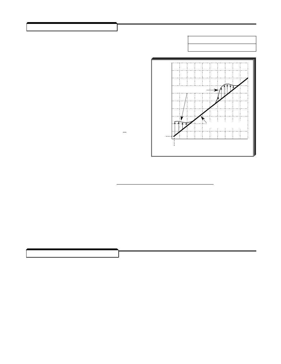
OUTPUT FREQUENCY
( HZ )
OUTPUT VOLTAGE
( VAC )
460
345
230
115
14 V
0
0
1.5 HZ
30
60
PROGRAMMED V/F PATTERN
(NO LOAD)
AUTO TORQUE BOOST
V/F PATTERN
Example of Torque Compensation
Operation
2.32 V/f PATTERN - STANDARD
Sn-02: V/f Pattern
This system constant is factory preset to
01
. Table 2-4 describes 14 other preset patterns,
one of which may be better suited for your specific application and load characteristics.
However, if none of these patterns are suitable, this constant can be set to
0F
(V/f
pattern - custom). The exact pattern is then defined by the settings of Cn-02 thru Cn-08,
described in paragraph 2.33.