Yaskawa GPD503 Drive User Manual
Page 62
2.20 MULTI-FUNCTION ANALOG MONITOR OUTPUT (Term. 21 & 22)
Sn-05: Operation Mode Select 2
Digit 4 [ X X X X ] : Multi-function
Analog Output
Factory setting: 0 X X X
Sn-09: Analog Monitor Selection
Digit 2 [ X X X X ] : Multi-function
Analog Output
Factory setting: X X 0 X
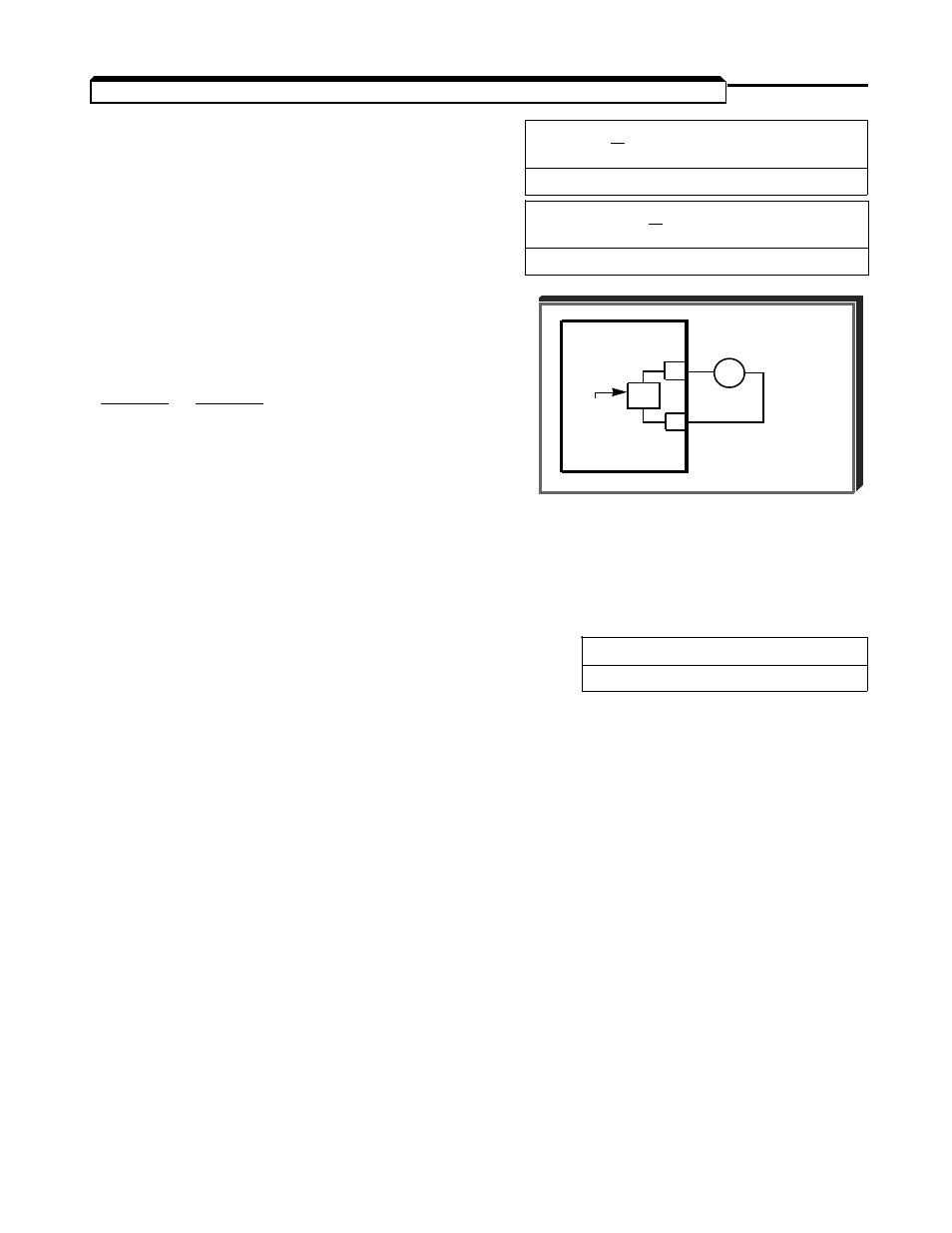
The monitor output provides a 0-10 Vdc signal
proportional to either output frequency, output
current, output voltage reference, or output power
between terminals 21 & 22:
Sn-05
Sn-09
0 X X X
X X 0 X = 0-10 Vdc proportional
to output frequency
1 X X X
X X 0 X = 0-10 Vdc proportional
to output current
0 X X X
X X 1 X = 0-10 Vdc proportional
to output voltage reference
1 X X X
X X 1 X = 0-10 Vdc proportional
to output power.
bn-11: Analog Monitor Channel 1 Gain
Factory Setting:
1.00
Range: 0.01 to 2.55
This constant is used to calibrate, in increments of 0.01, either the frequency or current
meter connected to terminals 21 & 22. This function is also used to calibrate Channel 1 of
one of the analog output options.
NOTE: When an analog output option is connected, bn-11 setting affects
both terminals 21 & 22 and the option terminals for Channel 1.
2-29
GPD 503
21
Analog
output 22
(0-10 Vdc)
MULTI-
FUNCTION
MONITOR
OUTPUT
+ –
FREQUENCY / CURRENT
METER
(1mA FULL SCALE)