Yaskawa GPD503 Drive User Manual
Page 3
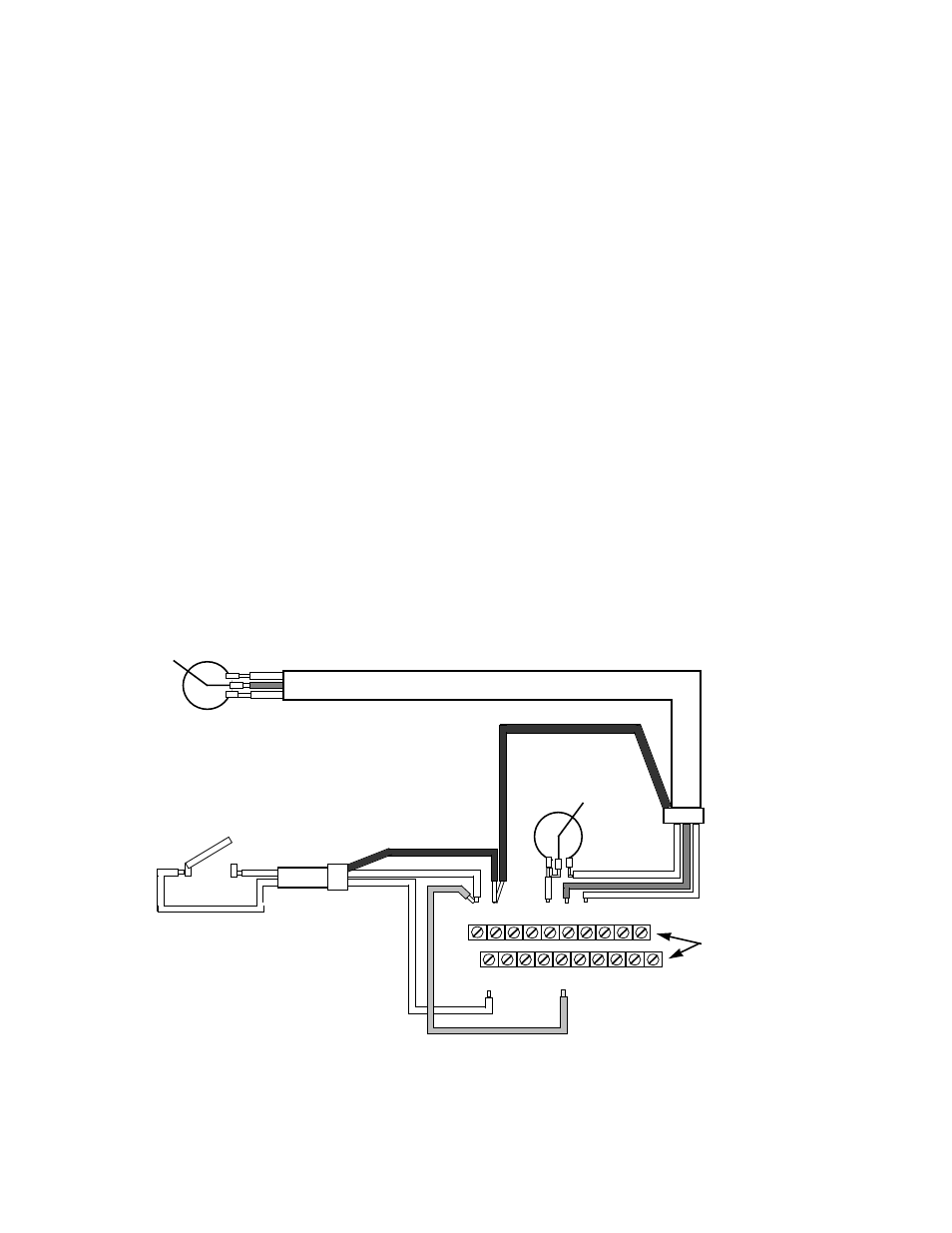
INSTALLATION OF EXTERNAL RUN/STOP SWITCH AND SPEED POTENTIOMETERS
IMPORTANT: Complete the INSTALLATION and KEYPAD OPERATION instructions before
attempting external control.
1. Disconnect power, remove cover, and wait for “CHARGE” light to go out.
2. Refer to the diagram below and connect a switch to terminals 1 and 11 using two conductor
shielded wire. This circuit is 24Vdc, very low current; use a quality rotary or toggle switch
(all wire should be 14-18AWG). Connect the shield to terminal 12 on the drive end only.
3. Install a single conductor “jumper” wire between drive terminals 5 and 11.
4. Connect a manual speed potentiometer rated 2000-3000 ohms, 1 watt minimum, using
three conductor shielded wire, with shield connected at terminal 12. Connect wires to the
potentiometer as shown, viewing potentiometer from the back. Trace wire shown closest to
the top in diagram (right side of potentiometer) and connect to terminal 17. Trace center
wire of potentiometer through and connect to terminal 16. The remaining wire will be
connected to the trim pot in step 5.
5. Connect a trim potentiometer rated 2000-3000 ohms, 1 watt minimum, as close to the drive
terminals as possible. Viewing the potentiometer from the back, connect a single conductor
wire from the left terminal to terminal 15 of the drive. Connect a short jumper wire between
the center and left terminals. Connect remaining wire from manual speed pot as shown.
- ii -
11 12 13 14 15 16 17 25 26 27
1 2 3 4 5 6 7 8 21 22
1R
Trim Pot
S1
STOP
RUN
SHIELD
WIRES
1RH
MANUAL SPEED
POTENTIOMETER
(REAR VIEW)
Shield wire
termination
GPD 503
Control Board
terminals
"Jumper
wire"