12 external fault inputs – Yaskawa GPD503 Drive User Manual
Page 46
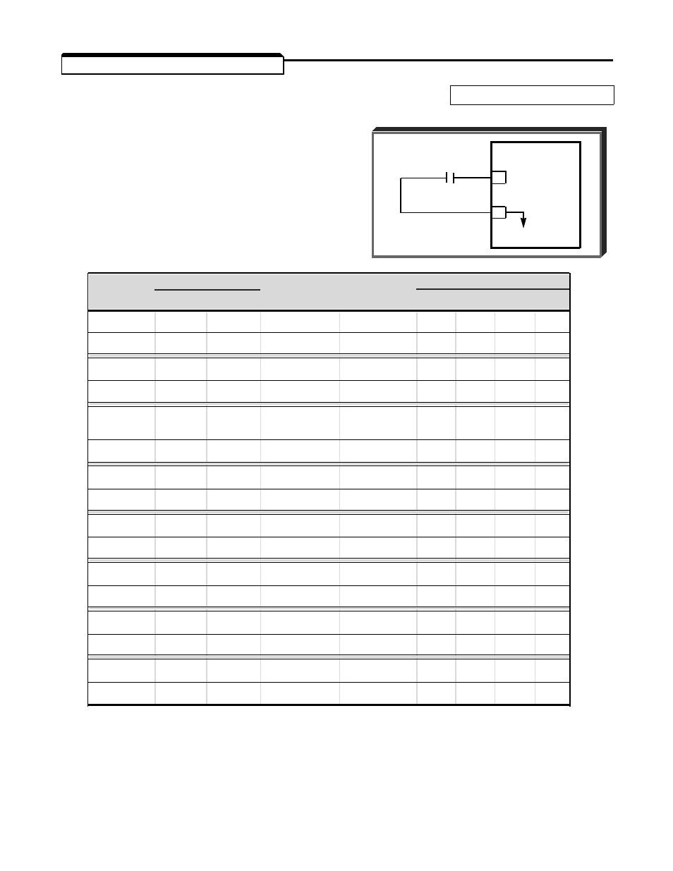
2.12 EXTERNAL FAULT INPUTS
A. Sn-12: External Fault Signal Input
Factory setting:
0100
(Terminal 3)
This constant determines how the GPD 503
responds to an external fault contact input on
terminal 3. The chart below lists the possible
settings, and indicates how the GPD 503 will
interpret the input signal.
Sn-12
Term. 3 (Note 1)
Always
During
Mode (Note 2)
Data
N.O. N.C.
Detected
Operation
0
1
2
3
0000
X
X
X
0001
X
X
X
0010
X
X
X
0011
X
X
X
0100
X
X
X
(Factory Set)
0101
X
X
X
0110
X
X
X
0111
X
X
X
1000
X
X
X
1001
X
X
X
1010
X
X
X
1011
X
X
X
1100
X
X
X
1101
X
X
X
1110
X
X
X
1111
X
X
X
NOTES
1.
N.O. = normally open contact; N.C. = normally closed contact.
2.
Mode 0 = Ramp to Stop (bn-02); Mode 1 = Coast to Stop;
Mode 2 = Emergency Stop (bn-04);
Mode 3 = Continue operation (minor fault).
EXTERNAL
FAULT
CONTACT
GPD 503
3
11
0V
Sn-12 Term. 3 (Note 1) Always
During
Mode (Note 2)
Data
N.O. N.C.
Detected
Operation
0
1
2
3
2-15
- Tag Generator (30 pages)
- MP3300iec (82 pages)
- 1000 Hz High Frequency (18 pages)
- 1000 Series (7 pages)
- PS-A10LB (39 pages)
- iQpump Micro User Manual (300 pages)
- 1000 Series Drive Option - Digital Input (30 pages)
- 1000 Series Drive Option - CANopen (39 pages)
- 1000 Series Drive Option - Analog Monitor (27 pages)
- 1000 Series Drive Option - CANopen Technical Manual (37 pages)
- 1000 Series Drive Option - CC-Link (38 pages)
- 1000 Series Drive Option - CC-Link Technical Manual (36 pages)
- 1000 Series Drive Option - DeviceNet (37 pages)
- 1000 Series Drive Option - DeviceNet Technical Manual (81 pages)
- 1000 Series Drive Option - MECHATROLINK-II (32 pages)
- 1000 Series Drive Option - Digital Output (31 pages)
- 1000 Series Drive Option - MECHATROLINK-II Technical Manual (41 pages)
- 1000 Series Drive Option - Profibus-DP (35 pages)
- AC Drive 1000-Series Option PG-RT3 Motor (36 pages)
- Z1000U HVAC MATRIX Drive Quick Start (378 pages)
- 1000 Series Operator Mounting Kit NEMA Type 4X (20 pages)
- 1000 Series Drive Option - Profibus-DP Technical Manual (44 pages)
- CopyUnitManager (38 pages)
- 1000 Series Option - JVOP-182 Remote LED (58 pages)
- 1000 Series Option - PG-X3 Line Driver (31 pages)
- SI-EN3 Technical Manual (68 pages)
- JVOP-181 (22 pages)
- JVOP-181 USB Copy Unit (2 pages)
- SI-EN3 (54 pages)
- MECHATROLINK-III (35 pages)
- SI-ET3 (49 pages)
- EtherNet/IP (50 pages)
- SI-EM3 (51 pages)
- 1000-Series Option PG-E3 Motor Encoder Feedback (33 pages)
- 1000-Series Option SI-EP3 PROFINET (56 pages)
- PROFINET (62 pages)
- AC Drive 1000-Series Option PG-RT3 Motor (45 pages)
- SI-EP3 PROFINET Technical Manual (53 pages)
- A1000 Drive Option - BACnet MS/TP (48 pages)
- 120 Series I/O Modules (308 pages)
- A1000 12-Pulse (92 pages)
- A1000 Drive Software Technical Manual (16 pages)
- A1000 Quick Start (2 pages)
- JUNMA Series AC SERVOMOTOR (1 page)
- A1000 Option DI-101 120 Vac Digital Input Option (24 pages)