2 control circuit – Yaskawa GPD503 Drive User Manual
Page 20
1.4 ELECTRICAL INSTALLATION Continued
1.4.2 Control Circuit
All basic control circuit (signal) interconnections are shown in the appropriate diagram:
• Interconnections for external two-wire control in combination with the Digital
Operator are shown in Figure 1-3 (for 230V or 460V rated drives) and Figure
1-5 (for 575V rated drives).
• Interconnections for external three-wire control in combination with the Digital
Operator are shown in Figure 1-4 (for 230V or 460V rated drives) and Figure
1-6 (for 575V rated drives).
Make wiring connections according to Figures 1-1 thru 1-4 and Table 1-3, observing the
following :
• Signal Leads : Terminals 1-8, 11-17, and 21-27.
• Control Leads : Terminals 9 & 10 and 18-20.
• Power Leads : Input Terminals L1 (R), L2 (S), and L3 (T), and Output Terminals
T1 (U), T2 (V), and T3 (W).
• Use twisted shielded or twisted-pair shielded wire (20-14 AWG (0.5-2mm
2
)for
1-60HP (CT); 18-14 AWG (0.75-2mm
2
) for 75-400HP (CT) ) for control and signal
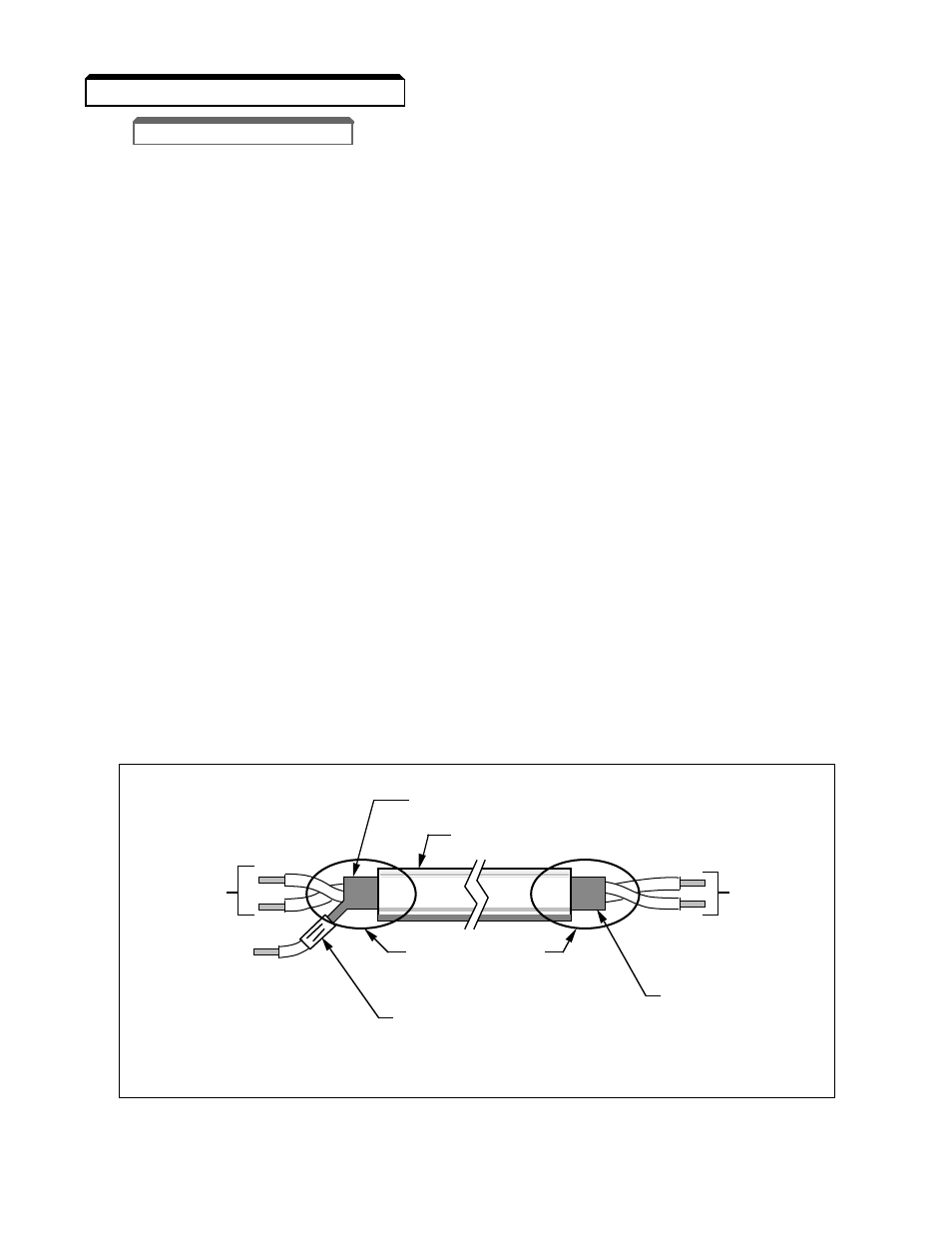
circuit leads. When using shielded wire, the shield sheath MUST be connected
at the GPD 503 ONLY (terminal 12). The other end should be dressed neatly and
left unconnected (floating). See Figure 1-1.
• Lead length should NOT EXCEED 164 feet (50 meters). Wire sizes should be
determined considering the voltage drop.
TO GPD 503
SIGNAL
TERMINALS
TO SHIELD
SHEATH
TERMINAL
(TERM. 12)
WRAP BOTH ENDS
OF SHEATH WITH
INSULATING TAPE
CRIMP
CONNECTION
SHIELD SHEATH
OUTER JACKET
DO NOT
CONNECT
TO
EXTERNAL
CIRCUIT
Figure 1-1. Shielded Sheath Termination
1-4