Caution – Yaskawa GPD503 Drive User Manual
Page 157

8. IMPORTANT:
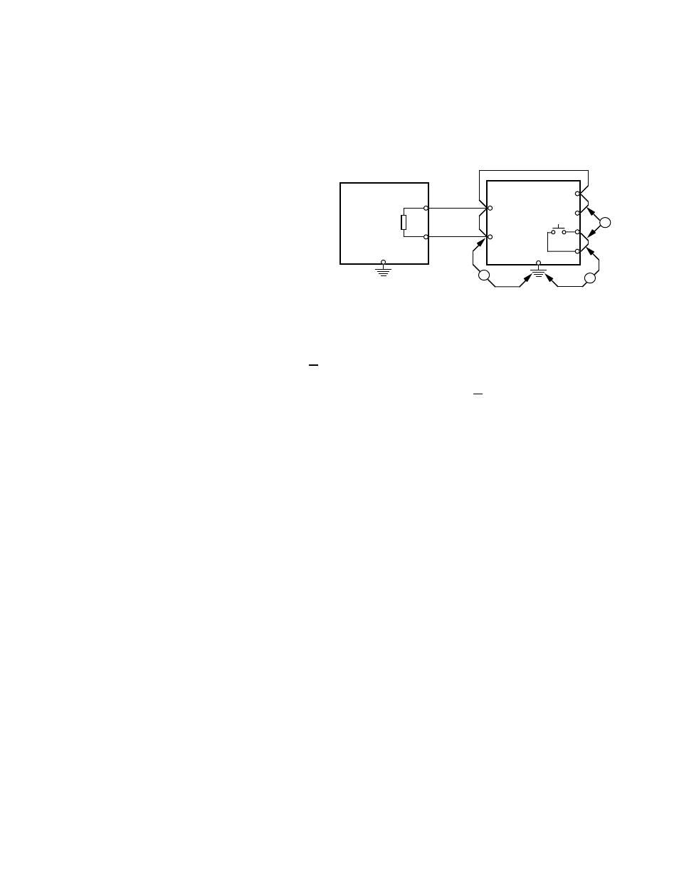
After wiring, test insulation resistance of each Braking Unit/Braking
Resistor Unit with a 900V megger as follows:
a.
Disconnect leads between the Braking Unit and the drive. If equipment
with semiconductors is connected across terminals 1 & 2 of the Braking
Unit, remove the wiring.
b.
Connect common leads
(jumpers) across Braking
Unit terminals N, P, Po,
and B, and across 3 & 4,
as shown in Figure A7-6.
c.
Measure the insulation
resistance at points a, b,
and c in Figure A7-6 with
the megger.
ADJUSTMENTS
9. ALL drives: Program Sn-10 to
X X 1 X
, to disable stall prevention during decel.
10. Only with Heat Sink Mount Resistor: Program Sn-11 to
X X X 1
, to enable overheat
protection for the braking resistor.
OPERATION CHECK
11. During dynamic braking operation, verify that the "BRAKE" lamp inside the Braking
Unit will be lit.
12. During dynamic braking operations, ensure that the required deceleration
characteristic is obtained. If not, contact MagneTek for assistance.
13. Reinstall and secure covers on the DB units and the drive.
CAUTION
During normal operation, the Braking Unit and the Braking Resistor Unit must
remain closed, since high voltage is applied to the dynamic braking circuit.
A7-8
BRAKING
RESISTOR
UNIT
BRAKING
UNIT
P
B
N
3
4
P
B
P
0
GND (E)
c
b
a
Figure A7-6. Megger Testing Set-up
