A7-4 – Yaskawa GPD503 Drive User Manual
Page 153
Braking Resistor Unit Installation (for 230V 1-10HP(CT), 460V 1-20HP(CT),
575V 2-25HP(CT) drives)
IMPORTANT
Since the Braking Resistor Unit generates heat during dynamic braking operation,
install it in a location away from other equipment which emits heat.
1. Mount the Braking Resistor Unit on a vertical surface, maintaining a minimum 1.18
inch (30 mm) clearance on each side and a minimum 5.91 inch (150 mm) clearance top
and bottom.
2. Remove the Braking Resistor
Unit front cover to access its
terminal block. Connect the
Braking Resistor Unit to the drive
and to external control circuitry
according to the chart at right and
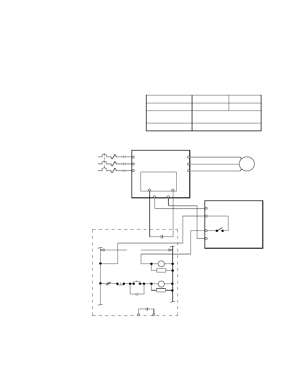
Figure A7-3.
4. Reinstall and
secure Braking
Resistor Unit front
cover and drive front
cover.
5. Proceed to step
10 on page A7-8.
A7-4
Figure A7-3. Wiring Braking Resistor Unit to Drive
(230V 1-10HP(CT), 460V 1-20HP(CT), 575V 2-25HP(CT))
T1
T2
T3
R
S
T
U
V
W
GPD 503
CONTROL
PCB
3
11
B1
B2
PART OF USER SUPPLIED
EXTERNAL
CIRCUIT
BRAKING
RESISTOR
UNIT
B
P
2
1
THG
THRX
1M
1M
1M
CB
L1
L2
L3
120VAC
THRX
FAULT
CONTACT
THRX
RC
1M
RC
1M
THRX
POWER
ON
POWER
OFF
Terminals
B, P
1, 2 *
Lead Size (AWG)
12-10
18-14 *
Lead Type
600V ethylene propylene
rubber insulated, or equivalent
Terminal Screw
M4
* Power leads for the Braking Resistor Unit generate high levels of
electrical noise; these signal leads must be grouped separately.