33 v/f pattern - custom – Yaskawa GPD503 Drive User Manual
Page 87
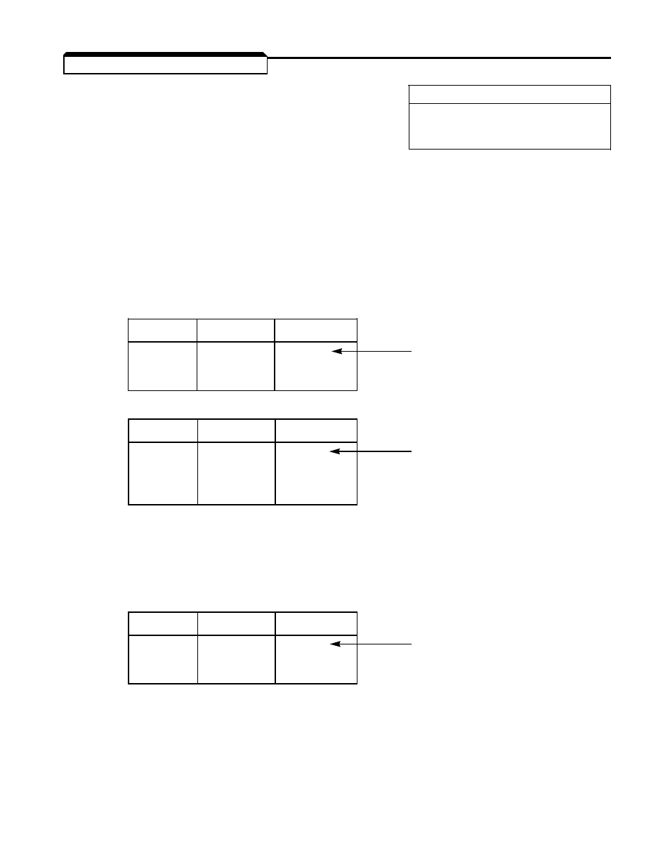
2.33 V/f PATTERN - CUSTOM
A.
Cn-01: Output Voltage Regulator
Factory Setting:
230 / 460 / 575
V
Range: 0.0 to 255.0 (230V)
0.0 to 510.0 (460V)
0.0 to 733.1 (575V)
This constant sets the output voltage to be regulated. If Sn-02 is set to a value in the
range
00
to
0E
, then changing Cn-01 will automatically effect the voltage constants
(Cn-03, Cn-06 and Cn-08; see section B of this feature description) proportionally. If
Sn-02 is
0F
, then Cn-01 has no effect on the voltage constants, and the output voltage
would be determined by the voltages programmed into Cn-03, Cn-06 and Cn-08.
NOTE: Before changing Cn-01, refer to the examples below.
EXAMPLES
:
230V Drive
V
IN
V
OUT
Cn-01
230
230
230
Factory Setting
230
208
208
208
208
208
460V Drive
V
IN
V
OUT
Cn-01
460
460
460
Factory Setting
460
400
400
380
380
380
460
380
460
*
* For this condition, Custom V/Hz Pattern should be used (Sn-02 =
0F
), and Cn-01 set to Input Voltage.
For 460V units only:
• If Cn-01
*
400, then overvoltage trip point = 800 Vdc
• If Cn-01
400, then overvoltage trip point = 700 Vdc.
575V Drive
V
IN
V
OUT
Cn-01
575
575
575
Factory Setting
500
500
500
575
500
575
*
* For this condition, Custom V/Hz Pattern should be used (Sn-02 =
0F
), and Cn-01 set to Input Voltage.
For 575V units only:
• If Cn-01
*
500, then overvoltage trip point = 1040 Vdc
• If Cn-01
500, then overvoltage trip point = 910 Vdc.
2-48