Yaskawa GPD503 Drive User Manual
Page 21
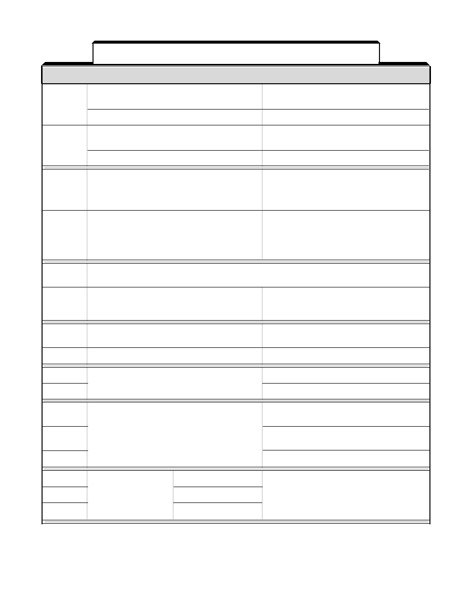
TERMINAL
FUNCTIONS
LEVELS
1
2-WIRE CONTROL: Forward Run / Stop signal
Run at closed, stop at open (See NOTE 2)
(See NOTE 1)
3-WIRE CONTROL: Run signal
Run at closed (See NOTE 2)
2
2-WIRE CONTROL: Reverse Run / Stop signal
Run at closed, stop at open (See NOTE 2)
(See NOTE 1)
3-WIRE CONTROL: Stop signal
Stop at open (See NOTE 2)
3
External fault input
Fault at closed (see NOTE 2). When the External
Fault input is applied, the GPD 503’s Fault relay
trips (shutdown) and the motor coasts to a stop.
The Digital Operator displays “
EF3 ” failure.
4
Fault Reset input (external)
Fault Reset at closed (see NOTE 2). The Fault
Reset input will reset the Fault relay, if the
GPD 503 is in “stopped” condition. Both Forward
Run/Stop signal and Reverse Run/Stop signal
must be OPEN.
5 - 8
External signal inputs (see NOTE 2); functions as defined by settings of system constants Sn-15 thru Sn-18.
See MULTI-FUNCTION INPUT TERMINALS in the PROGRAMMABLE FEATURES section of this manual.
9, 10
Multi-function contact output.
Contact capacity:
One of 18 functions are available, by setting
250 Vac at 1A or below
of system constant Sn-20. (N.O.)
30 Vdc at 1A or below
11
Sequence control input common
Sequence control input 0 V
for terminals (1 - 8).
12
Connection for shield sheath of signal leads
– – – –
13
0 to +10V (20K ohms)
Auto frequency reference input
14
4-20 mA (250 ohms)
15
Manual frequency reference power supply
+15V (Control power supply for frequency setting:
max 20 mA)
16
Multi-function analog input; function of input signal
0 to +10V/100% (20K ohms)
is selected by setting of system constant Sn-19
17
Multi-function analog input common
0 V
18
Closed at fault
Contact capacity:
Fault contact output
19
(N.O./N.C.)
Open at fault
250 Vac at 1A or below
20
Common
30 Vdc at 1A or below
TERMINAL
FUNCTIONS
LEVELS
Table 1-3. Terminal Functions and Signals of Control Circuit
1-5