18 multi-function analog input (term. 16) – Yaskawa GPD503 Drive User Manual
Page 55
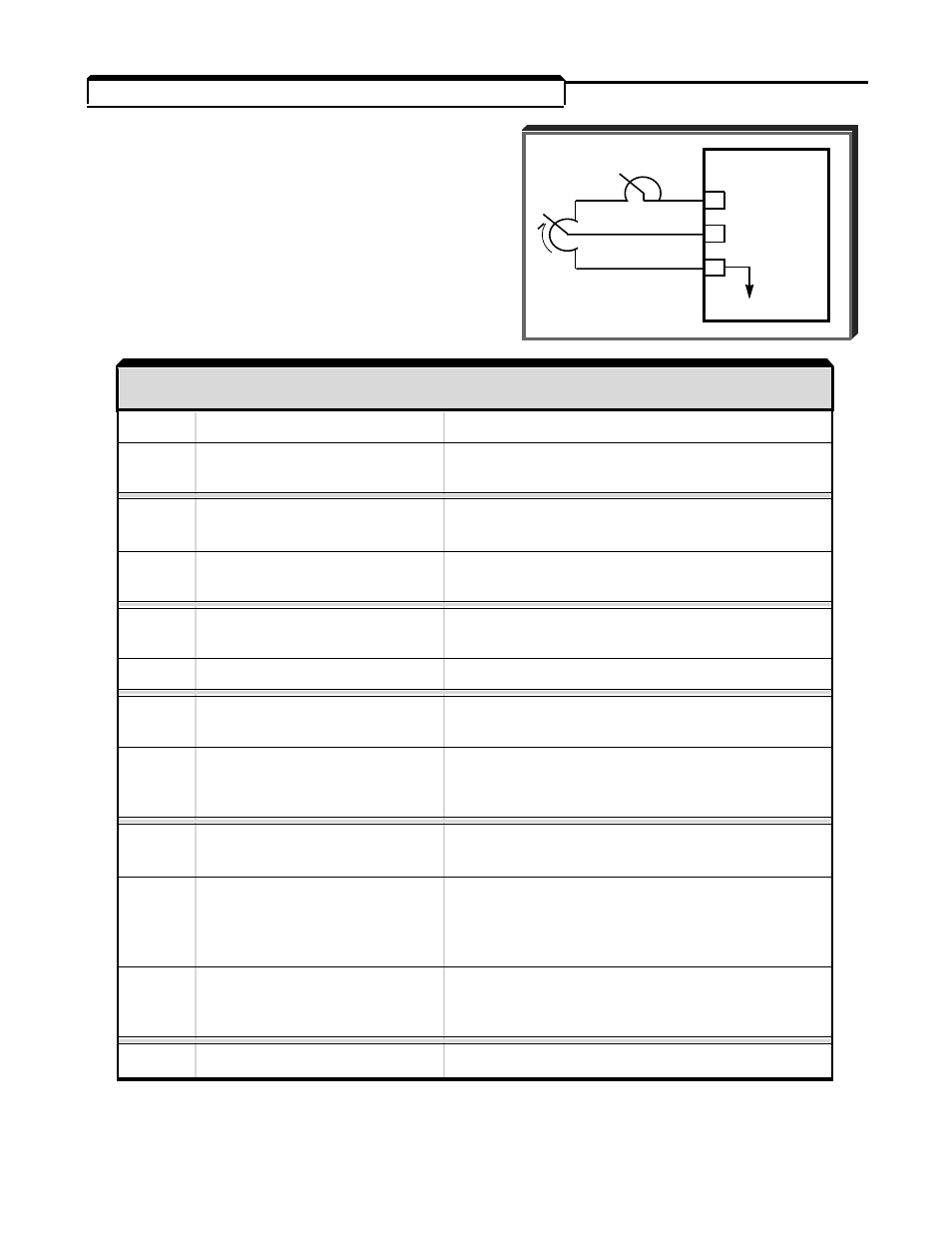
2.18 MULTI-FUNCTION ANALOG INPUT (Term. 16)
Sn-19: Multi-function Analog Input
(Term. 16)
Programming Sn-19 per the chart below con-
figures terminal 16 for analog control. The
figures on the next page show how each setting
configures the analog input.
SET
VALUE
FUNCTION
REMARKS
00
Manual reference
External reference input
01
Frequency reference gain
Total gain = Internal gain (bn-05) x FGAINE
(FGAINE)
02
Frequency reference bias 1 Total bias = Internal bias (bn-06) + FBIAS1
(FBIAS1) *
03
Frequency reference bias 2 Total bias = Internal bias (bn-06) + FBIAS2
(FBIAS2) (+/-) *
04
Overtorque detection
Internal overtorque detection level
level
(Cn-26) disabled
05
VBIAS **
VBIAS addition after V/f conversion
06
Accel/decel time
Accel/decel time varied by analog input
coefficient
07
DC injection braking
DC injection braking current varied by
current adjust
analog input (10V/drive rated current);
internal setting (Cn-11) ineffective
08
Stall prevention level
Stall prevention level (Cn-30 = 100% level)
during running
varied by analog input
09
Frequency reference
Frequency reference lower limit is set by
lower limit
analog input. Either Cn-15 setting value
or analog input, whichever is greater,
becomes effective.
0A
Setting prohibited
Analog input sets a fourth prohibited
frequency 4
frequency, in addition to those set by Cn-16
thru Cn-18.
0b
-
FF
Not Used
* FBIAS1 and FBIAS2 are based on Fmax (Cn-02).
** DC boost adjust on V/Hz curve.
1R
GPD 503
15 +15V
16 0-10V
(20K
1
)
17
C
SET
VALUE
FUNCTION
REMARKS
2-22