2 pr eset ting aut o matically – HEIDENHAIN iTNC 530 (340 49x-04) Touch Probe Cycles User Manual
Page 88
88
3 Touch Probe Cycles for Automatic Workpiece Inspection
3.2 Pr
eset
ting aut
o
matically
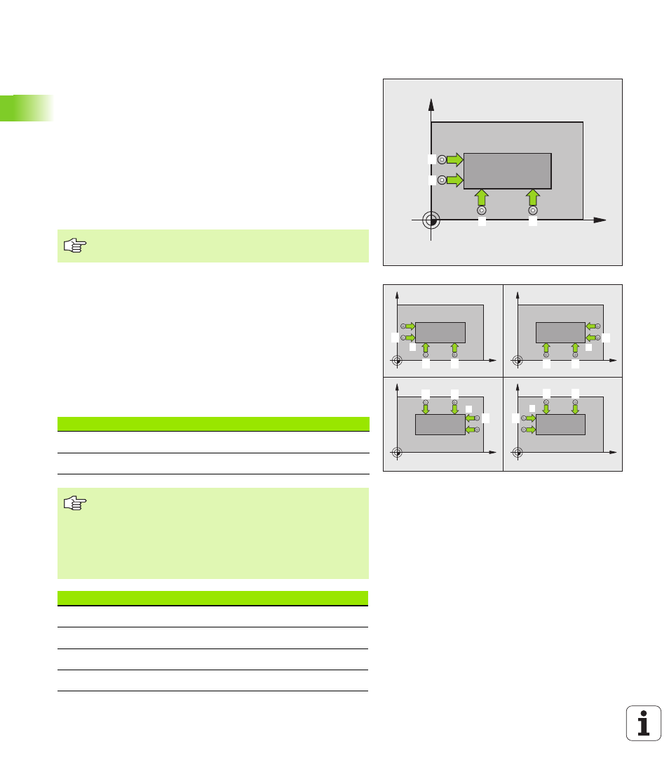
DATUM FROM OUTSIDE OF CORNER
(touch probe cycle 414, DIN/ISO: G414)
Touch probe cycle 414 finds the intersection of two lines and defines
it as the datum. If desired, the TNC can also enter the intersection into
a datum table or preset table.
1
Following the positioning logic (see “Running touch probe cycles”
on page 26), the TNC positions the touch probe at rapid traverse
(value from MP6150 or MP6361) to the first touch point
1
(see figure
at upper right). The TNC offsets the touch probe by the safety
clearance in the direction opposite the respective traverse direction.
2
Then the touch probe moves to the entered measuring height and
probes the first touch point at the probing feed rate (MP6120 or
MP6360). The TNC derives the probing direction automatically
from the programmed 3rd measuring point.
3
Then the touch probe moves to the next starting position
2
and
probes the second position.
4
The TNC positions the probe to starting point
3
and then to starting
point
4
to probe the third and fourth touch points.
5
Finally the TNC returns the touch probe to the clearance height and
processes the determined datum depending on the cycle
parameters Q303 and Q305 (see “Saving the calculated datum”
on page 69) and saves the coordinates of the determined corner in
the Q parameters listed below
6
If desired, the TNC subsequently measures the datum in the touch
probe axis in a separate probing.
X
Y
1
2
4
3
X
Y
X
Y
X
Y
X
Y
A
B
C
D
1
2
3
2
1
3
1
2
3
2
1
3
The TNC always measures the first line in the direction of
the minor axis of the working plane.
Parameter number
Meaning
Q151
Actual value of corner in reference axis
Q152
Actual value of corner in minor axis
Before programming, note the following
By defining the positions of the measuring points
1
and
3
you also determine the corner at which the TNC sets the
datum (see figure at right and table at lower right).
Before a cycle definition you must have programmed a
tool call to define the touch probe axis.
Corner
X coordinate
Y coordinate
A
Point
1
greater than point
3
Point
1
less than point
3
B
Point
1
less than point
3
Point
1
less than point
3
C
Point
1
less than point
3
Point
1
greater than point
3
D
Point
1
greater than point
3
Point
1
greater than point
3