3 a u to matic w o rk piece measur ement – HEIDENHAIN iTNC 530 (340 49x-04) Touch Probe Cycles User Manual
Page 122
122
3 Touch Probe Cycles for Automatic Workpiece Inspection
3.3 A
u
to
matic W
o
rk
piece Measur
ement
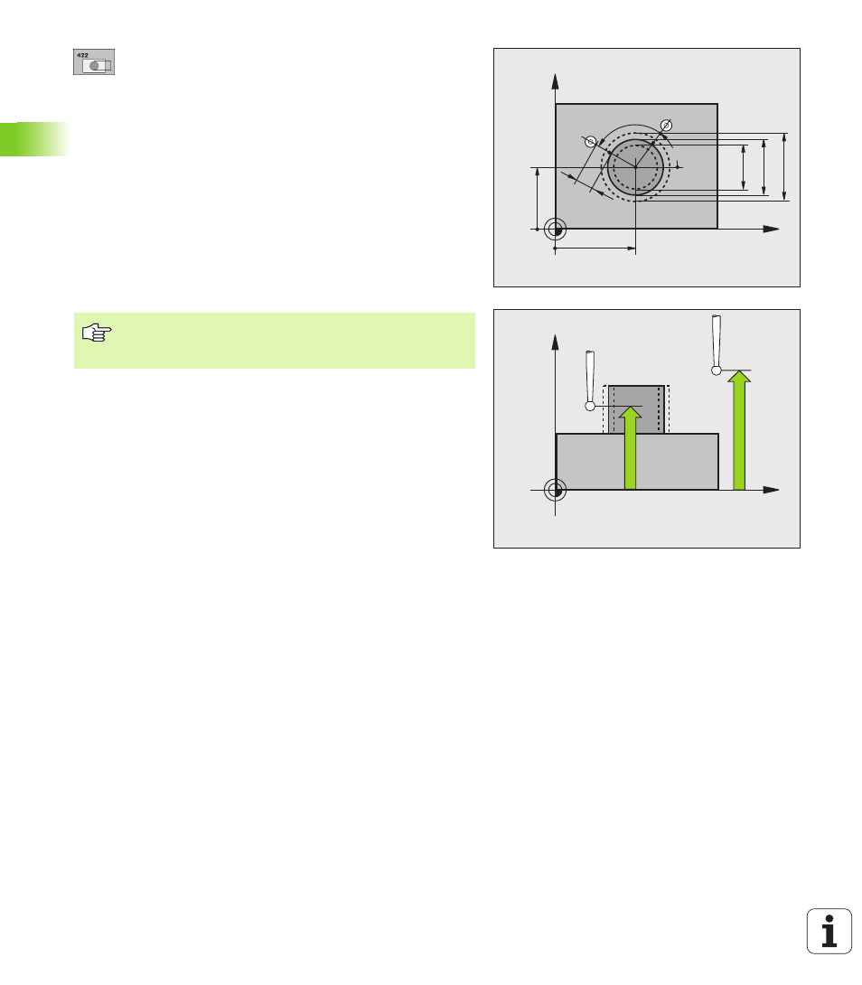
Center in 1st axis
Q273 (absolute value): Center of
the stud in the reference axis of the working plane.
Center in 2nd axis
Q274 (absolute value): Center of
the stud in the minor axis of the working plane.
Nominal diameter
Q262: Enter the diameter of the
stud.
Starting angle
Q325 (absolute): Angle between the
reference axis of the working plane and the first touch
point.
Stepping angle
Q247 (incremental): Angle between
two measuring points. The algebraic sign of the
stepping angle determines the direction of rotation
(negative = clockwise). If you wish to probe a circular
arc instead of a complete circle, then program the
stepping angle to be less than 90°.
Measuring height in the touch probe axis
Q261
(absolute): Coordinate of the ball tip center (= touch
point) in the touch probe axis in which the
measurement is to be made.
Setup clearance
Q320 (incremental): Additional
distance between measuring point and ball tip. Q320
is added to MP6140.
Clearance height
Q260 (absolute): Coordinate in the
touch probe axis at which no collision between tool
and workpiece (fixtures) can occur.
Traversing to clearance height
Q301: Definition of
how the touch probe is to move between the
measuring points:
0: Move at measuring height between measuring
points
1: Move at clearance height between measuring
points
Maximum dimension of size for stud
Q277:
Maximum permissible dimension for the stud.
Minimum dimension of size for the stud
Q278:
Minimum permissible dimension for the stud.
Tolerance value for center 1st axis
Q279:
Permissible position deviation in the reference axis of
the working plane.
Tolerance value for center 2nd axis
Q280:
Permissible position deviation in the minor axis of the
working plane.
X
Y
Q325
Q247
Q278
Q262
Q277
Q274
±Q280
Q273
±Q279
MP6140
+
Q320
X
Z
Q261
Q260
The smaller the angle, the less accurately the TNC can
calculate the dimensions of the stud. Minimum input
value: 5°