3 a u to matic w o rk piece measur ement – HEIDENHAIN iTNC 530 (340 49x-04) Touch Probe Cycles User Manual
Page 114
114
3 Touch Probe Cycles for Automatic Workpiece Inspection
3.3 A
u
to
matic W
o
rk
piece Measur
ement
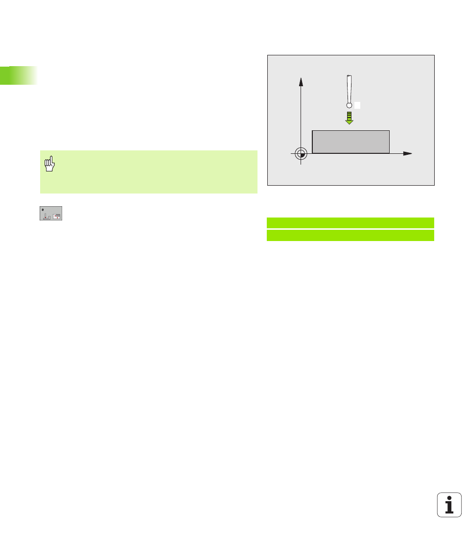
REFERENCE PLANE (touch probe cycle 0,
DIN/ISO: G55)
1
The touch probe moves at rapid traverse (value from MP6150 or
MP6361) to the starting position
1
programmed in the cycle.
2
Then the touch probe approaches the workpiece at the feed rate
assigned in MP6120 or MP6360. The probing direction is to be
defined in the cycle.
3
After the TNC has saved the position, the probe retracts to the
starting point and saves the measured coordinate in a Q
parameter. The TNC also stores the coordinates of the touch probe
position at the time of the triggering signal in the parameters Q115
to Q119. For the values in these parameters the TNC does not
account for the stylus length and radius.
Parameter number for result:
Enter the number of
the Q parameter to which you want to assign the
coordinate.
Probing axis/Probing direction:
Enter the probing
axis with the axis selection keys or ASCII keyboard
and the algebraic sign for the probing direction.
Confirm your entry with the ENT key.
Position value:
Use the axis selection keys or the
ASCII keyboard to enter all coordinates of the nominal
pre-positioning point values for the touch probe.
To conclude the input, press the ENT key.
X
Z
1
Before programming, note the following
Pre-position the touch probe in order to avoid a collision
when the programmed pre-positioning point is
approached.
Example: NC blocks
67 TCH PROBE 0.0 REF. PLANE Q5 X-
68 TCH PROBE 0.1 X+5 Y+0 Z-5