1 measur ing w o rk piece misalignment – HEIDENHAIN iTNC 530 (340 49x-04) Touch Probe Cycles User Manual
Page 56
56
3 Touch Probe Cycles for Automatic Workpiece Inspection
3.1 Measur
ing W
o
rk
piece Misalignment
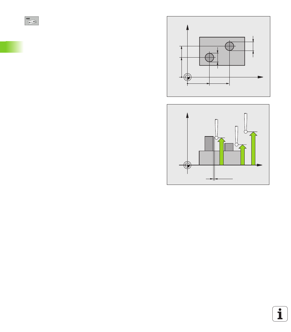
First stud: Center in 1st axis
(absolute): center of
the first stud in the reference axis of the working
plane.
First stud: Center in 2nd axis
Q269 (absolute):
center of the first stud in the minor axis of the
working plane.
Diameter of stud 1
Q313: Approximate diameter of
the 1st stud. Enter a value that is more likely to be too
large than too small.
Measuring height 1 in the probe axis
Q261
(absolute): Coordinate of the ball tip center (= touch
point in the touch probe axis) at which stud 1 is to be
measured.
Second stud: Center in 1st axis
Q270 (absolute):
center of the second stud in the reference axis of the
working plane.
Second stud: Center in 2nd axis
Q271 (absolute):
center of the second stud in the minor axis of the
working plane.
Diameter of stud 2
Q314: Approximate diameter of
the 2nd stud. Enter a value that is more likely to be
too large than too small.
Measuring height 2 in the probe axis
Q315
(absolute): Coordinate of the ball tip center (= touch
point in the touch probe axis) at which stud 2 is to be
measured.
Setup clearance
Q320 (incremental): Additional
distance between measuring point and ball tip. Q320
is added to MP6140.
Clearance height
Q260 (absolute): Coordinate in the
touch probe axis at which no collision between tool
and workpiece (fixtures) can occur.
X
Y
Q271
Q269
Q268
Q270
Q313
Q314
X
Z
Q261
Q260
Q315
MP6140
+
Q320