2 pr eset ting aut o matically – HEIDENHAIN iTNC 530 (340 49x-04) Touch Probe Cycles User Manual
Page 74
74
3 Touch Probe Cycles for Automatic Workpiece Inspection
3.2 Pr
eset
ting aut
o
matically
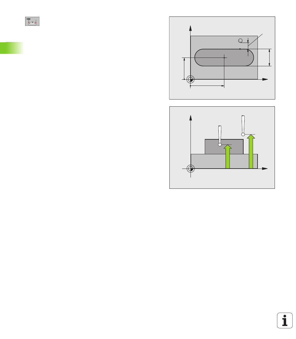
Center in 1st axis
Q321 (absolute): Center of the
ridge in the reference axis of the working plane.
Center in 2nd axis
Q322 (absolute): Center of the
ridge in the minor axis of the working plane.
Width of ridge
Q311 (incremental): Width of the
ridge, regardless of its position in the working plane.
Measuring axis (1=1st axis / 2=2nd axis)
Q272:
Axis in which the measurement is to be made:
1: Reference axis = measuring axis
2: Minor axis = measuring axis
Measuring height in the touch probe axis
Q261
(absolute): Coordinate of the ball tip center (= touch
point) in the touch probe axis in which the
measurement is to be made.
Setup clearance
Q320 (incremental): Additional
distance between measuring point and ball tip. Q320
is added to MP6140.
Clearance height
Q260 (absolute): Coordinate in the
touch probe axis at which no collision between tool
and workpiece (fixtures) can occur.
Number in table
Q305: Enter the number in the
datum/preset table in which the TNC is to save the
coordinates of the ridge center. If you enter Q305=0,
the TNC automatically sets the display so that the
new datum is on the slot center.
New datum
Q405 (absolute): Coordinate in the
measuring axis at which the TNC should set the
calculated ridge center. Basic setting = 0
X
Y
Q322
Q321
Q31
1
MP6140
+
Q320
X
Z
Q261
Q260