1 measur ing w o rk piece misalignment – HEIDENHAIN iTNC 530 (340 49x-04) Touch Probe Cycles User Manual
Page 62
62
3 Touch Probe Cycles for Automatic Workpiece Inspection
3.1 Measur
ing W
o
rk
piece Misalignment
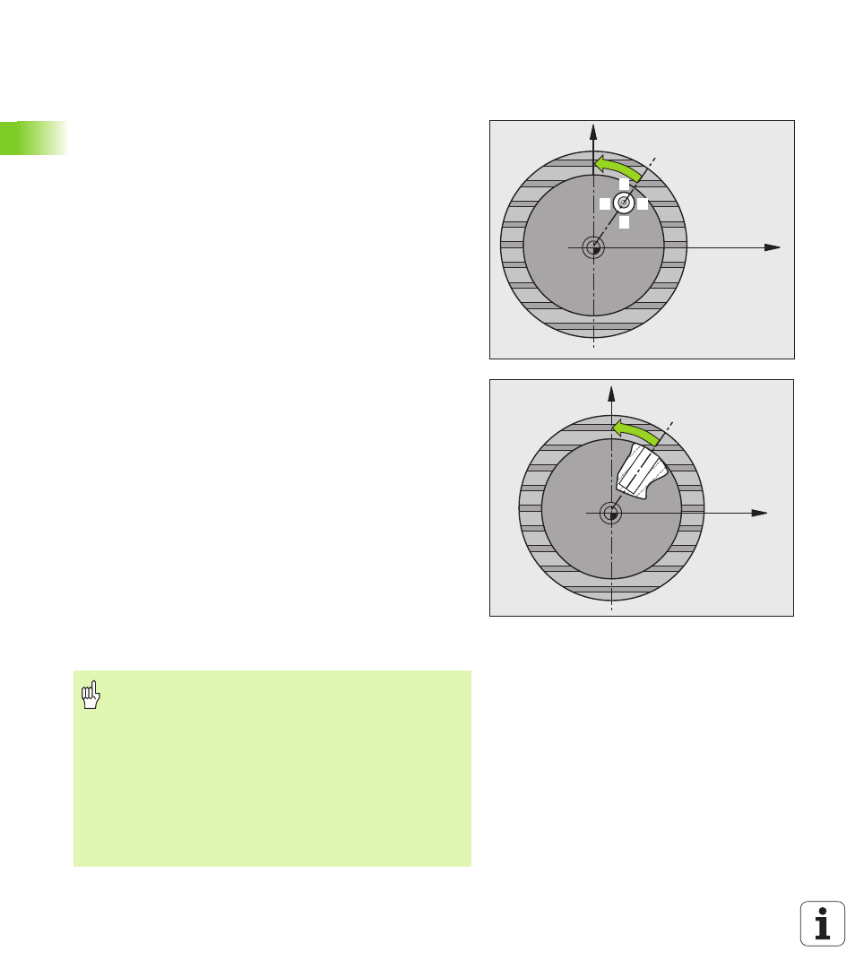
Compensating workpiece misalignment by
rotating the C axis (touch probe cycle 405,
DIN/ISO: G405)
With touch probe cycle 405, you can measure
the angular offset between the positive Y axis of the active
coordinate system and the center of a hole, or
the angular offset between the nominal position and the actual
position of a hole center.
The TNC compensates the determined angular offset by rotating the
C axis. The workpiece can be clamped in any position on the rotary
table, but the Y coordinate of the hole must be positive. If you
measure the angular misalignment of the hole with touch probe axis Y
(horizontal position of the hole), it may be necessary to execute the
cycle more than once because the measuring strategy causes an
inaccuracy of approx. 1% of the misalignment.
1
The TNC positions the touch probe to the starting points at rapid
traverse (value from MP6150 or MP6361) following the positioning
logic (see “Running touch probe cycles” on page 26) to the
starting point
1
. The TNC calculates the probe starting points from
the data in the cycle and the safety clearance from MP6140.
2
Then the touch probe moves to the entered measuring height and
probes the first touch point at the probing feed rate (MP6120 or
MP6360). The TNC derives the probing direction automatically
from the programmed starting angle.
3
Then the touch probe moves in a circular arc either at measuring
height or at clearance height to the next starting point
2
and probes
the second touch point.
4
The TNC positions the probe to starting point
3
and then to starting
point
4
to probe the third and fourth touch points and positions the
touch probe on the hole centers measured.
5
Finally the TNC returns the touch probe to the clearance height and
aligns the workpiece by rotating the table. The TNC rotates the
rotary table so that the hole center after compensation lies in the
direction of the positive Y axis, or on the nominal position of the
hole center—both with a vertical and horizontal touch probe axis.
The measured angular misalignment is also available in parameter
Q150.
X
Y
1
2
4
3
X
Y
Before programming, note the following
To prevent a collision between the touch probe and the
workpiece, enter a low estimate for the nominal diameter
of the pocket (or hole).
If the dimensions of the pocket and the safety clearance
do not permit pre-positioning in the proximity of the touch
points, the TNC always starts probing from the center of
the pocket. In this case the touch probe does not return to
the clearance height between the four measuring points.
Before a cycle definition you must have programmed a
tool call to define the touch probe axis.