1 measur ing w o rk piece misalignment – HEIDENHAIN iTNC 530 (340 49x-04) Touch Probe Cycles User Manual
Page 65
HEIDENHAIN iTNC 530
65
3.1 Measur
ing W
o
rk
piece Misalignment
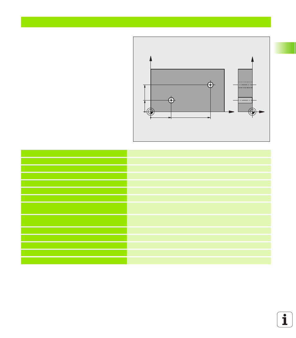
Example: Determining a basic rotation from two holes
0 BEGIN PGM CYC401 MM
1 TOOL CALL 0 Z
2 TCH PROBE 401 ROT 2 HOLES
Q268=+25
;1ST CENTER IN 1ST AXIS
Center of the 1st hole: X coordinate
Q269=+15
;1ST CENTER IN 2ND AXIS
Center of the 1st hole: Y coordinate
Q270=+80
;2ND CENTER IN 1ST AXIS
Center of the 2nd hole: X coordinate
Q271=+35
;2ND CENTER IN 2ND AXIS
Center of the 2nd hole: Y coordinate
Q261=-5
;MEASURING HEIGHT
Coordinate in the touch probe axis in which the measurement is
made
Q260=+20
;CLEARANCE HEIGHT
Height in the touch probe axis at which the probe can traverse
without collision
Q307=+0
;PRESET BASIC ROTATION
Angle of the reference line
Q402=1
;ALIGNMENT
Compensate misalignment by rotating the rotary table
Q337=1
;SET TO ZERO
Set the display to zero after the alignment
3 CALL PGM 35K47
Part program call
4 END PGM CYC401 MM
X
Y
25
35
Z
Y
80
15