3 a u to matic w o rk piece measur ement – HEIDENHAIN iTNC 530 (340 49x-04) Touch Probe Cycles User Manual
Page 128
128
3 Touch Probe Cycles for Automatic Workpiece Inspection
3.3 A
u
to
matic W
o
rk
piece Measur
ement
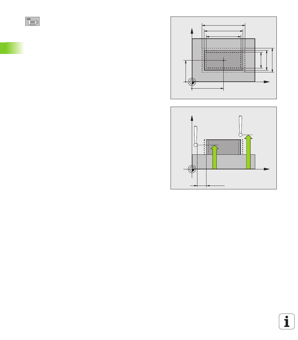
Center in 1st axis
Q273 (absolute value): Center of
the stud in the reference axis of the working plane.
Center in 2nd axis
Q274 (absolute value): Center of
the stud in the minor axis of the working plane.
First side length
Q282: stud length, parallel to the
reference axis of the working plane
Second side length
Q283: stud length, parallel to the
secondary axis of the working plane
Measuring height in the touch probe axis
Q261
(absolute): Coordinate of the ball tip center (= touch
point) in the touch probe axis in which the
measurement is to be made.
Setup clearance
Q320 (incremental): Additional
distance between measuring point and ball tip. Q320
is added to MP6140.
Clearance height
Q260 (absolute): Coordinate in the
touch probe axis at which no collision between tool
and workpiece (fixtures) can occur.
Traversing to clearance height
Q301: Definition of
how the touch probe is to move between the
measuring points:
0: Move at measuring height between measuring
points
1: Move at clearance height between measuring
points
Max. size limit 1st side length
Q284: Maximum
permissible length of the stud.
Min. size limit 1st side length
Q285: Minimum
permissible length of the stud.
Max. size limit 2nd side length
Q286: Maximum
permissible width of the stud.
Min. size limit 2nd side length
Q287: Minimum
permissible width of the stud.
Tolerance value for center 1st axis
Q279:
Permissible position deviation in the reference axis of
the working plane.
Tolerance value for center 2nd axis
Q280:
Permissible position deviation in the minor axis of the
working plane.
X
Y
Q287
Q285
Q274
±Q280
Q273
±Q279
Q283
Q286
Q282
Q284
X
Z
Q260
Q261
MP6140
+
Q320