1 measur ing w o rk piece misalignment – HEIDENHAIN iTNC 530 (340 49x-04) Touch Probe Cycles User Manual
Page 52
52
3 Touch Probe Cycles for Automatic Workpiece Inspection
3.1 Measur
ing W
o
rk
piece Misalignment
BASIC ROTATION from two holes (touch probe
cycle 401, DIN/ISO: G401)
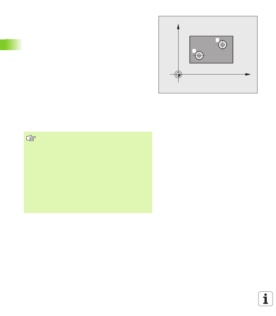
The touch probe cycle 401 measures the centers of two holes. Then
the TNC calculates the angle between the reference axis in the
working plane and the line connecting the two hole centers. With the
basic rotation function, the TNC compensates the calculated value
(See also \gCompensating Workpiece Misalignment” on page 35). As
an alternative, you can also compensate the determined misalignment
by rotating the rotary table.
1
Following the positioning logic (see “Running touch probe cycles”
on page 26), the TNC positions the touch probe at rapid traverse
(value from MP6150 or MP6361) to the point entered as center of
the first hole
1
.
2
Then the probe moves to the entered measuring height and
probes four points to find the first hole center.
3
The touch probe returns to the clearance height and then to the
position entered as center of the second hole
2
.
4
The TNC moves the touch probe to the entered measuring height
and probes four points to find the second hole center.
5
Then the TNC returns the touch probe to the clearance height and
performs the basic rotation.
X
Y
1
2
Before programming, note the following
Before a cycle definition you must have programmed a
tool call to define the touch probe axis.
The TNC will reset an active basic rotation at the beginning
of the cycle.
This touch probe cycle is not allowed when the tilted
working plane function is active.
If you want to compensate the misalignment by rotating
the rotary table, the TNC will automatically use the
following rotary axes:
C for tool axis Z
B for tool axis Y
A for tool axis X