HEIDENHAIN MANUALplus 4110 Pilot User Manual
Page 96
96
End-f
ace mac
hining
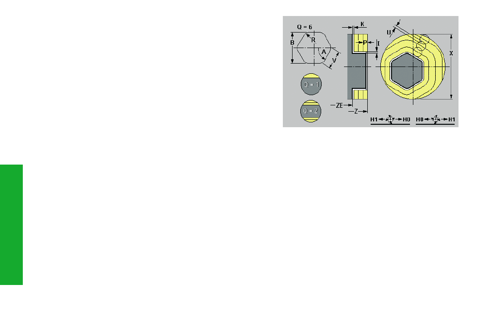
End-face surface milling cycle G797
Depending on “Q“, G797 mills surface, a polygon or the figure defined in
the command after G797.
If “Q=0“, one of the following figures is programmed in the next com-
mand, followed by a G80:
• G304 – Circle
• G305 – Rectangle
• G307 – Polygon
A polygon defined with G797 (Q>0) is in the center. A figure defined in
the next command may also be positioned off-center.
Parameters
X:
Border diameter
Z, ZE:
Reference edge, lower edge of milling
B:
Width across flats – not applicable when Q=0
• when Q=1: B is the remaining thickness
• when Q
2: B is the width across flats
V:
Edge length – not applicable when Q=0
R:
Chamfer/rounding – not applicable when Q=0
• R<0: Chamfer length
• R>0: Rounding radius
A:
Inclination angle (reference: see support graphics) – not
applicable when Q=0
Q:
Number of surfaces (0
Q 127) – default: 0
• Q=0: Figure description follows G797
• Q=1: One surface
• Q=2: Two surfaces offset by 180°
• Q=3: Triangle
• Q=4: Rectangle, square
• Q>4: Polygon
P:
Maximum infeed – default: in one infeed
U:
Overlap factor – (minimum) overlapping =
U*cutter diameter – default: 0.5
I, K:
Contour-parallel oversize, in infeed direction
F:
Infeed rate (for depth infeed) – default:
active feed rate
E:
Reduced feed rate for circular elements –
default: current feed rate
H:
Cutting direction – default: 0
• H=0: Up-cut milling
• H=1: Down-cut milling
O:
Roughing/finishing – default: 0
• O=0: Roughing
• O=1: Finishing
J:
Uni-/bidirectional (when Q=1 or Q=2)
• J=0: Unidirectional
• J=1: Bidirectional