HEIDENHAIN MANUALplus 4110 Pilot User Manual
Page 47
47
ICP Programming
Thread undercut DIN 76
Undercut DIN 509 E
Undercut DIN 509 F
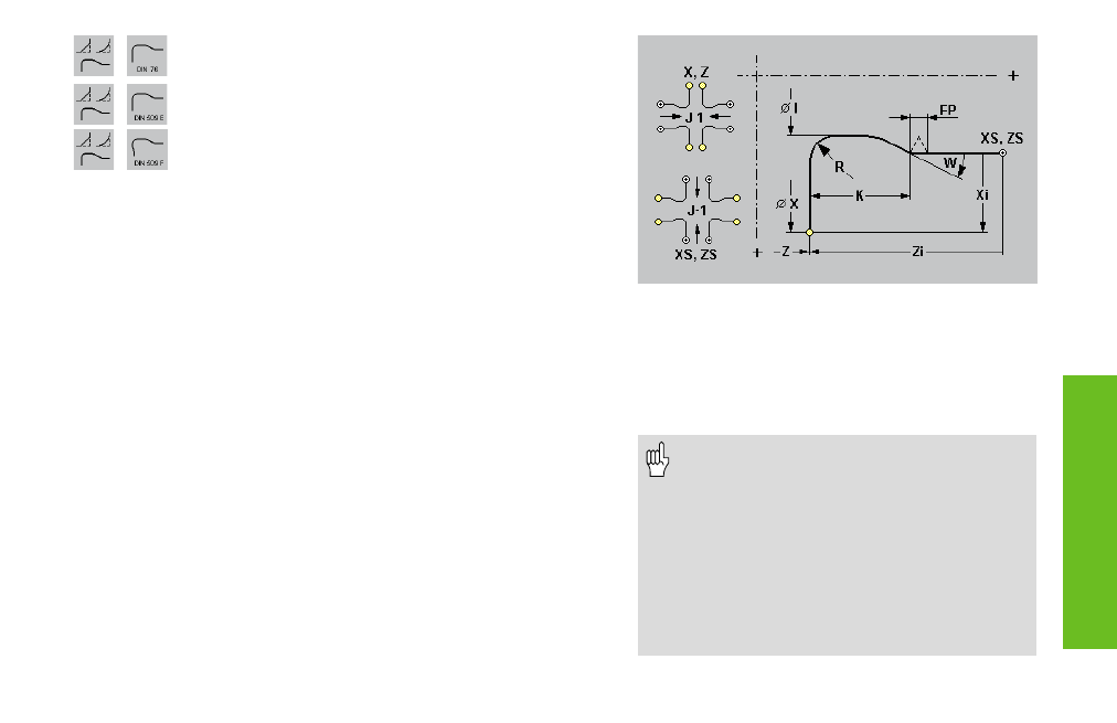
An “undercut” consists of a longitudinal element, an undercut and a
transverse element. You can start the undercut definition with either the
longitudinal or the transverse element.
Thread undercut: the diameter of the longitudinal element represents the
thread diameter (or, with internal threads, the core diameter).
Parameters that are not defined are automatically calculated from the
standard table. Also for a thread undercut:
• “FP“ is calculated from “XS“
• “I, K, W, and R“ are calculated from “FP“
Parameters (depending on the type of the undercut)
XS, ZS:
Start point of the undercut
X, Z:
End point of the undercut
FP:
Thread pitch
I:
Undercut diameter – default: value from the standard table
K:
Undercut length – default: value from the standard table
W:
Undercut angle – default: value from the standard table
R:
Undercut radius – default: value from the standard table
P:
Transverse depth– default: value from the standard table
A:
Transverse angle– default: value from the standard table
U:
Finishing oversize– default: no finishing oversize
J:
Element position– default: 1
• J=1: Undercut begins with longitudinal
element
• J=–1: Undercut begins with transverse
element
F:
Special feed
• The “element position J” cannot be en-
tered when superimposing the undercut
and cannot be changed when program-
ming changes to ICP contours.
• If you are programming an internal thread,
it is advisable to preset the “FP” since the
diameter of the longitudinal element is not
the thread diameter. If you have
MANUALplus calculate the thread pitch au-
tomatically, slight deviations may occur.