Nlec screen – HEIDENHAIN ND 1300 VED and Crosshair Systems User Manual
Page 269
249
11
Setup
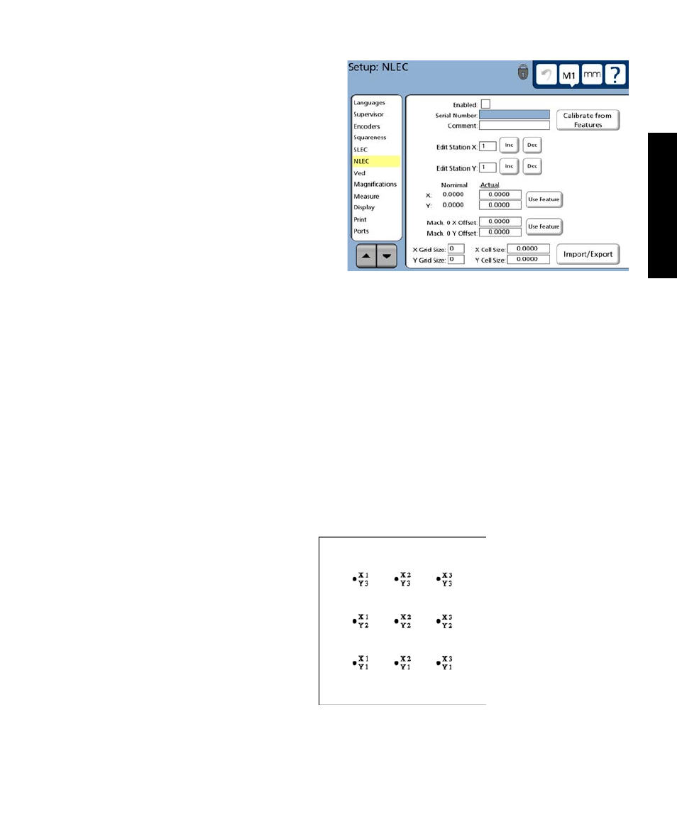
NLEC Screen
The NLEC screen contains fields for enabling and
configuring nonlinear error correction (NLEC) for
the X and Y encoder axes.
Nonlinear error correction minimizes or elimi-
nates the small inaccuracies in the X-Y measure-
ment plane due to encoder linearity, mounting and
machine-travel imperfections. Error correction
coefficients are obtained by measuring a certified
calibration grid. When the grid is measured, mea-
sured values are compared to either the ideal grid
values as described by the Grid Size and Cell Size fields, or to the certified grid values listed in an artifact
calibration file (.acf file). This comparison of measured values to ideal or actual values results in the final
NLEC.txt file that contains the error corrections for all measured grid locations. When NLEC is enabled,
the corrections will applied across the entire range of X-Y measurement to minimize or eliminate the inac-
curacies mentioned earlier.
.acf Files
When no .acf file is used, the calibration grid values are assumed to be ideal. When grid certification values
are available, an .acf file can be created easily using a word processor application. The format of the .acf
file is shown here with an example 3 X 3 grid and corresponding example .acf file. Create a text file of
actual grid values from the certification sheet and save the file using the nlec.acf file name and extension.
.acf file format
Unit of measure Skew axis
Size of Y cells Size of X cells
Number of X points Number of Y points
First X grid value First Y grid value
Next X grid value First Y grid value
Next X grid value First Y grid value
. .
. .
. .
Next X grid value Last Y grid value
Last X grid value Last Y grid value
Example .acf file
mm X
25.4 25.4
3 3
0.0000 0.0000
25.4003 0.0001
50.7998 0.0003
-0.0002 24.3997
25.4001 25.4004
50.8003 24.3999
0.0001 50.8001
25.4004 50.8004
Example 3 X 3 grid
NLEC Screen