HEIDENHAIN ND 1300 VED and Crosshair Systems User Manual
Page 266

246
QC-300 Series User’s Guide
SLEC (Segmented linear error correction)
SLEC compensates for encoder non-linearities by applying correction values to individual nonlinear seg-
ments. These SLEC correction values are created by the QC-300 system using data provided by the user
in the SLEC Setup screen. The SLEC setup data provided by the user consists of Standard (certified) and
Observed (measured) values of a standard, or standards that cover the entire range of axis motion.
The SLEC measurements can divide the axis range of motion into up to 150 segments. The example
diagrammed on the next page shows standard values compared to observed values for 6 segments. The
deviation (difference between standard and observed) is also shown. Segments are defined as any straight
line on the graph of deviations, beginning with segment zero.
The standard and observed values at the end of each segment are entered as data for a station in the SLEC
Setup screen. For example, the standard and observed values at the end of segment 0 on the diagram are 40
and 40, and are entered into the Standard and Observed data fields for station 1.
When the procedure is complete and setup data are entered, correction values will be calculated for the
encoder based on the standard and observed values at the end of the segments. The procedure for configur-
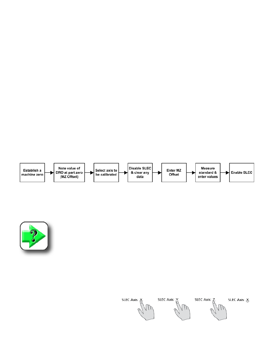
ing the SLEC error correction is diagrammed and explained below.
1 Cycle the power to establish a repeatable machine zero. You will be prompted to move the encoders
to cross reference marks or perform a hard stop to the establish machine zero. Perform the machine zero
operation.
NOTE
If a hard stop zero is performed, the same stop will be required each time the QC-300
is started.
2 The length of the calibration standard should cover as much of the range of axis motion as possible.
Move the stage to position the encoder of the axis being calibrated at the beginning (part zero position) of
the calibration standard. Make a note of this calibration axis value shown in the DRO; this will be entered
later as the machine zero (MZ) Offset.
3 Access the setup menu, touch the
SLEC menu item and then touch the Axis
choice field repeatedly to cycle to the axis
that will be calibrated.
