Installation – Grass Valley NV9649 v.1.1 User Manual
Page 24
12
Installation
Installation
Installation
Follow these steps to install a NV9649 control panel:
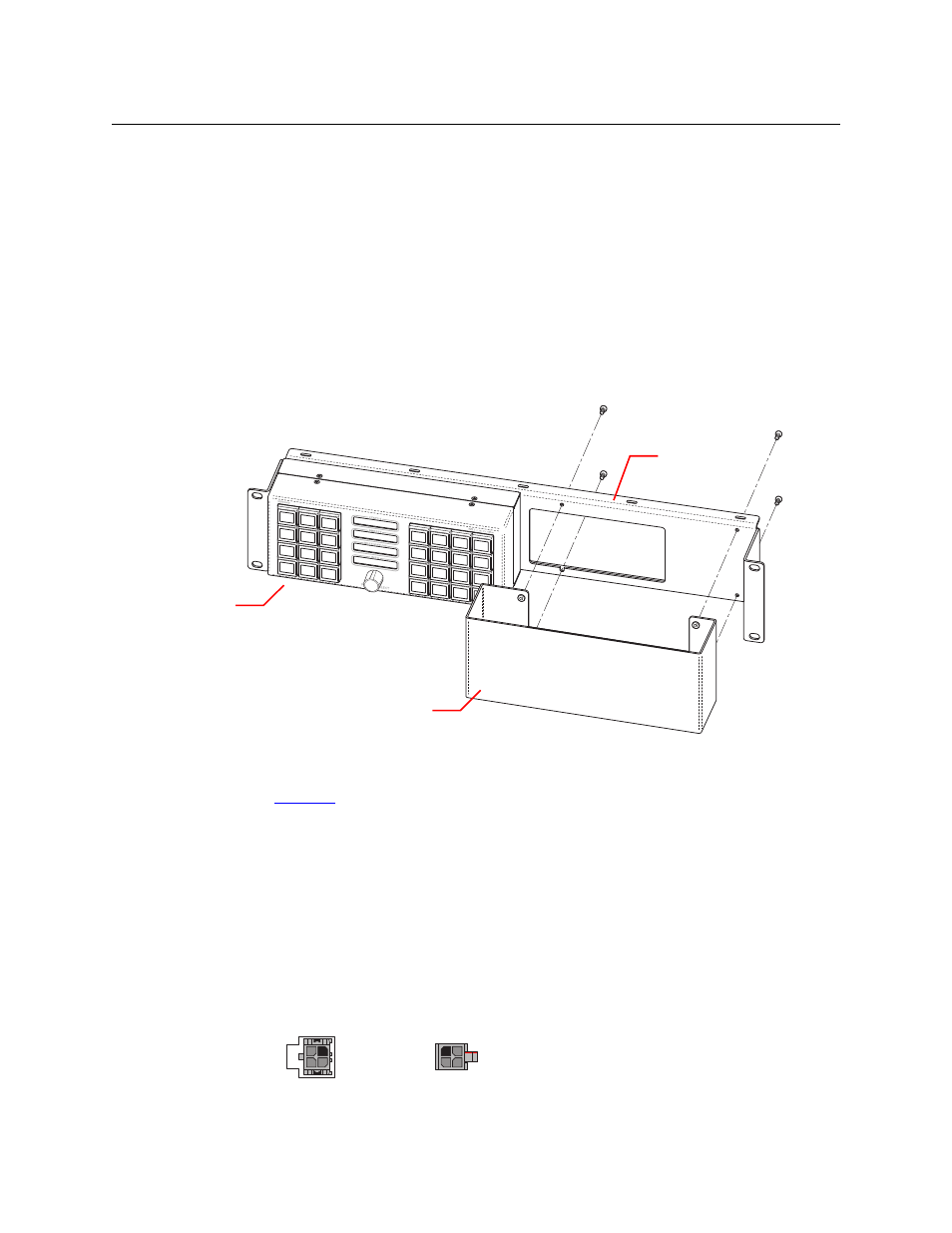
1 Mount, and secure, the panel(s) in the rack.
The NV9649 is designed to mount in a 19” rack. Rack-mounting is not a requirement.
The NV9649 is a 2RU half-width panel: you can install two of them side by side in a rack. Rack
mounting (either one or two NV9649s) requires a rack mounting bracket such as the one in
Grass Valley’s NV9649-48-RMK (rack-mounting kit). The kit contains two parts, (1) the bracket
itself and (2) a filler plate for brackets that will hold only one panel. The kit provides 8 mount-
ing screws for attaching the panels to the bracket.
The NV9649 mounts on the kit’s bracket using 4 screws. The bracket has two apertures in
which the connectors at the rear of the panel are exposed:
The filler plate and the NV9649 attach to the bracket in the same way. Each may be placed
on either side of the bracket.
See
Drawings
on page 83 for bracket dimensions.
Once the panel(s) are attached to the bracket, you can place the bracket in position in your
rack. Attach the bracket to the rack frame, using screws appropriate for your rack. The
bracket’s mounting slots are spaced 3.00” (76.2 mm) vertically and allow approximately 1/8”
(3 mm) of movement horizontally.
2 We assume that you have an Ethernet switch connected to the “Panel and Router Network”
port of your system controller. Connect an Ethernet cable from that switch to the RJ-45 port
at the rear of the NV9649.
3 Connect one or both power supplies. First connect the 4-pin connector to PS1 or PS2 on the
rear of the router. The connectors are keyed and snap into place. There is only one way they
fit. Do not force them. Then connect the power supply to AC power.
Rack-Mounting
Bracket
FIller Plate
NV9649
2
1
4
3
Receptacle
n.c.
n.c.
GND
12VDC
4
3
2
1
GND
12 VDC
n.c.
n.c.
Plug