Replacing the motherboard – Visara CNA-8000 User Manual
Page 107

CNA-8000 Users Guide and Maintenance Manual
707157-001
8-3
Replacing the Motherboard
Warning: Be sure to disconnect the power supply before opening the
chassis.
Removal Procedure
1. Lay the chassis on a flat surface.
2. Remove the top cover of the unit.
3. Remove rear fans (2) and air shrouds (if present) from the chassis.
4. Using a marking pen, place a mark on the heat sink on the front or
rear to denote its placement. This will help keep the orientation of
the processor and the heatsink due to the thermal compound when
the two components are separated. It will provide a better thermal
connection when the two components are reinstalled.
5. Remove the 4 screws holding the CPU heat sink and carefully
remove.
Caution: The heat sink may be adhered to the top of the CPU due to the
thermal compound applied during assembly.
6. Raise the locking lever on the socket holding the CPU and
carefully remove. Set aside on antistatic foam.
7. Remove the RAM sticks from their sockets. Set aside on antistatic
foam or antistatic pouch.
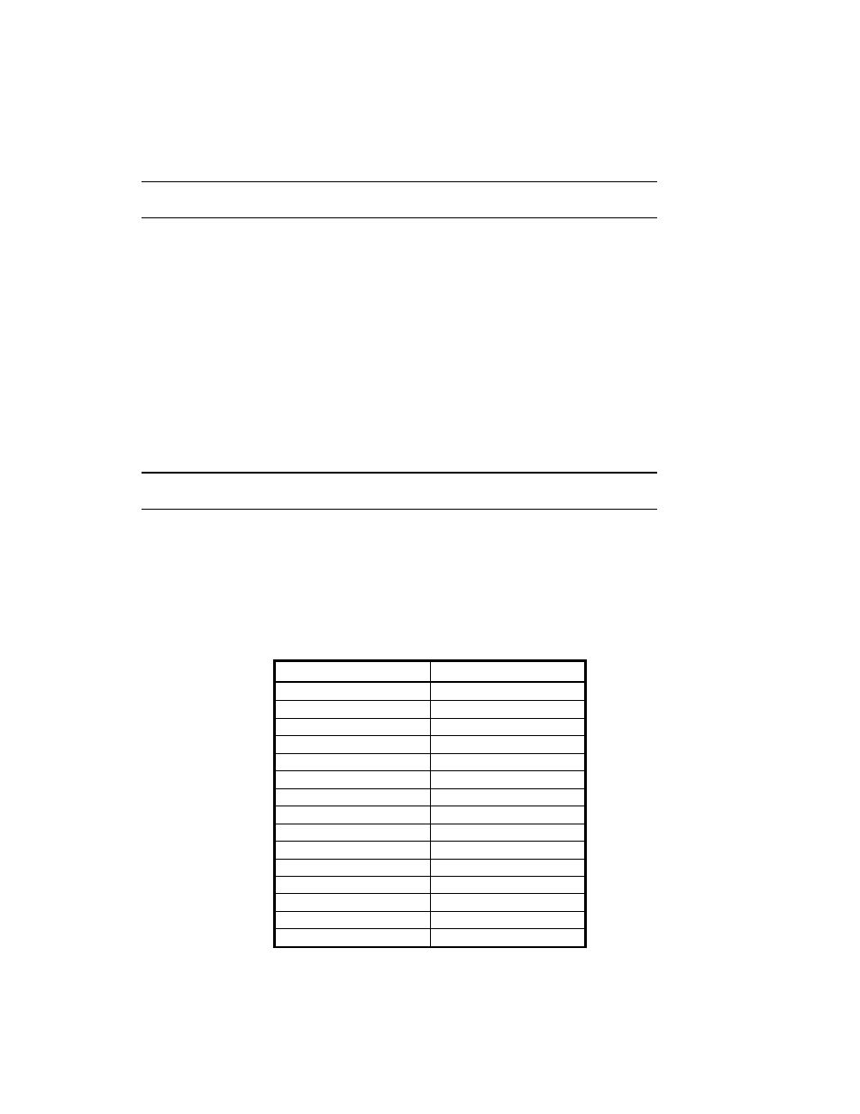
8. The following table lists the cables that must be disconnected from
the motherboard to facilitate proper removal:
CABLE HEADER
ATX Power
JPW1
+12V 8 Pin
JPW2
SMB Power (I
2
C) PW4
8.0cm Fan
FAN4
8.0cm Fan
FAN3
8.0cm Fan
FAN2
8.0cm Fan
FAN1
8.0cm Fan
FAN5
CPU Fan
FAN6
DVD Data
SATA0
FDD Data
J27
SATA#0 SATA4
SATA#1 SATA5
LED Panel 16-Pin 3M
JF1
Chassis Intrusion
JL1
10. Remove the 9 Type A (6-32) screws fastening the motherboard to
the chassis.
