5 display panel, 1 alphanumeric display, When in the bus display mode (bus led on). a – Measurement Computing Analyzer488 User Manual
Page 49: Tindicates a trigger point, Indicates relative addressing, Bus indicates bus display mode
Section 3
Front Panel Operation
3.3
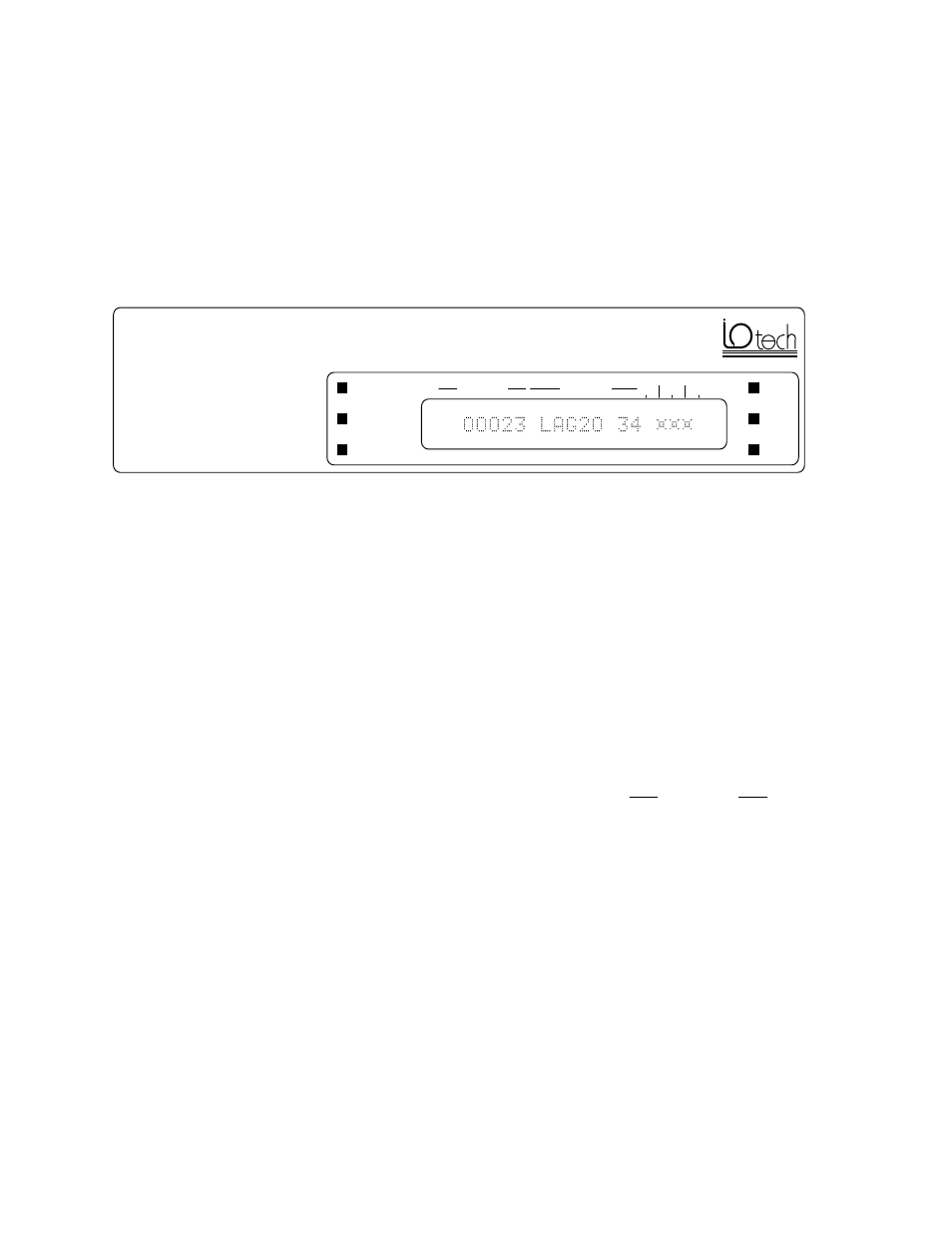
3.5 Display Panel
The display panel of the Analyzer488 contains a 20 character
alphanumeric vacuum fluorescent display and LED indicators. The display
panel shows the state of the bus, the contents of record memory, and status,
help and other messages. LED indicators show the display mode and the state
of the handshaking lines.
S
R
Q
IFC
REN
ATN
BUS
MEMORY
RECORD
NRFD
NDAC
DAV
EOI
LSB
LOCATION
MESSAGE
Analyzer488
IEEE 488 Bus Analyzer
3.5.1 Alphanumeric Display
-LOCATION-
The -LOCATION- area shows either record memory
location addresses when in the memory view mode
(MEMORY LED on), or the message
BUS
when in the bus
display mode (BUS LED on). A
T
in the first column
means that the location is a trigger point. A
+
or
-
means
that relative addressing format is used. Note that when
recording (RECORD LED on), the -LOCATION- area
might change. See paragraph 3.7 for examples.
LOCATION
address in the record memory
00008
T
indicates a trigger point
T00055
+
indicates relative addressing
+00001
-
indicates relative addressing
-00002
bus
indicates bus display mode
BUS
-MESSAGE- The -MESSAGE- area displays bus data in bus message