View of the analyzer488 rear panel – Measurement Computing Analyzer488 User Manual
Page 41
Section 2
Getting Started
2.19
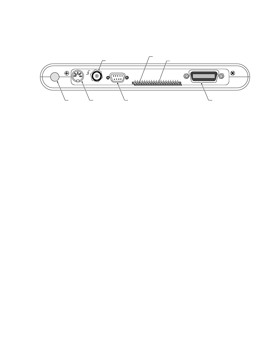
View of the Analyzer488 Rear Panel
IOtech, Inc.
Made in U.S.A
SRQ
ATN
EOI
DIO8
DIO7
DIO6
DIO5
DIO4
DIO3
DIO2
DIO1
GND
REN
IFC
NFRD
NDAC
DAV
CMP
GND
RS-232
POWER
TRIG
OUT
IEEE 488
BUS TEST POINTS
On/Off Switch
Power Supply
Connector
RS-232 Serial Port
IEEE 488 Port
Unbuffered IEEE 488 Test Points
Trigger Output BNC
Comparator Output
1. On/Off switch - Depress the power switch to apply power to the
Analyzer488.
2. Power Supply connector - Plug the cable from the external power supply
into this jack.
3. Trigger Output - When the trigger point event is recorded by the
Analyzer488, the trigger output will transition from a low (0) to a high (1)
logic level and stay high.
4. RS-232 Port - Connect a 9 pin RS-232 cable to this connector to use the
Analyzer488 with a serial host or serial printer.
5. Edge Card Connector - All IEEE 488 bus lines are brought out to this
connector for use with an oscilloscope or logic analyzer. Also a compare
(CMP) output is provided that pulses whenever the trigger match pattern
appears on the bus
6. IEEE 488 Connector - Connect a standard IEEE 488 cable to this
connector to use the Analyzer488 with other bus devices.