Data i/o interface connector (j8), 3 data i/o interface connector (j8) – Comtech EF Data SDM-300A User Manual
Page 84
SDM-300A Satellite Modem
Revision 6
External Connections
MN/SDM300A.IOM
4–6
4.1.3
Data I/O Interface Connector (J8)
The Data I/O interface connector conducts data input and output signals to and from the modem,
and connects to the customer’s terrestrial equipment, breakout panel, or protection switch. The
modem is currently available with a choice of four Data I/O connectors, as follows:
• 25-pin D connector is the standard connector shipped with a base platform modem.
• 50-pin D connector is the standard connector when the modem is ordered with the
optional overhead PCB or if the overhead PCB has been installed in the field.
• 50-pin D that can be ordered with the basic modem, but it does not include the
Overhead Card. This is used with breakout panels and switches.
• 37-pin D is an alternate connector available upon special request for the base platform
modem.
• 34-pin Winchester is an alternate connector available upon special request for the base
platform modem.
• 50-pin D connector is used when the optional Flex MUX Overhead Board is installed.
• 100-pin D connector is used when the Optional 8-Channel MUX Board is installed.
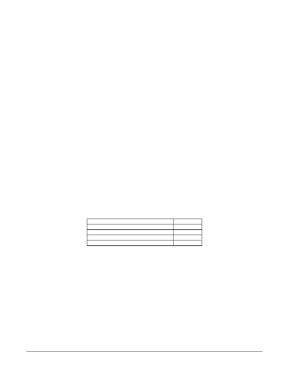
The Data I/O pinout is different for each of the interface configurations. For pinout information,
refer to the appropriate table as follows:
Standard 25-pin D connector
Table 4-4
Optional: 34-pin Winchester connector
Table 4-5
Optional: 37-pin D connector
Table 4-6
Optional: 50-pin D connector
Table 4-7
Optional: 15-pin D connector
Table 4-8