Comtech EF Data SDM-300A User Manual
Page 385
SDM-300A Satellite Modem
Revision 6
Specifications
MN/SDM300A.IOM
19–29
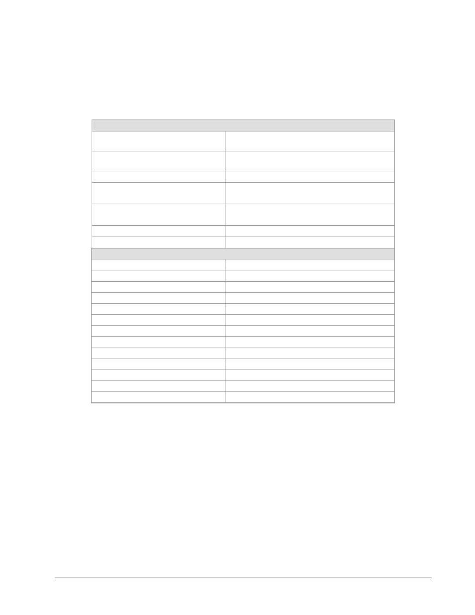
19.9.3
V.35 Specification V.10, V.11 Specification, Circuit Supported
V.35 Specification V.10, V.11 Specification, Circuit Supported
Circuit Supported
SD, SCT, SCTE, RD, SCR, DSR, RLSD, RTS, CTS,
MC, DSR, LL
Driver Amplitude (RD, SCR, SCTE, CTS,
RLSD, DSR, SCTE)
± 0.5V-PK, ± 20% differential, into 100Ω
Amplitude (SCT, SD, RTS, LL, MC)
± 0.2V Minimum into 100Ω
Polarity (SD, SCT, SCTE, RD, SCR)
True when B positive with respect to A
False when A positive with respect to B
Polarity (RTS, CTS, DSR, RLSD)
True when < -0.2V with respect to ground
False when > +0.2V with respect to ground
Phasing (SCTE, SCR)
False-to-True transition nominally in center of data bit
Symmetry (SCT, SCTE, SCR)
50%,
± 5%
Circuit Assignments
SD-A, SD-B
Send Data
SCT-A, SCT-B
Serial Clock Transmit
RD-A, RD-B
Receive Data
SCR-A, SCR-B
Serial Clock Receive
SCTE-A, SCTE-B
Transmitter Signal Timing
MC-A, MC-B
Master Clock
RTS
Request to Send
CTS
Clear to Send
DSR
Data Set Ready
RLSD
Receive Line Signal Detect
LL Local
Loopback
MF
Mod Fault (ttl)
DF
Demod Fault (ttl)