Fault connector and pinouts (j7), 2 fault connector and pinouts (j7) – Comtech EF Data SDM-300A User Manual
Page 83
SDM-300A Satellite Modem
Revision 6
External Connections
MN/SDM300A.IOM
4–5
4.1.2
Fault Connector and Pinouts (J7)
The fault connector provides Form C contact closures for fault reporting. The three Form C
summary fault contacts, ratings 1A maximum at 24 VDC, 0.5A at 120 VAC, are Modulator,
Demodulator, and Common Equipment.
The fault interface connection is a 9-pin subminiature female D connector (J7) located on the rear
panel of the modem. Screw locks are provided for mechanical security on the mating connector.
Refer to Table 4-3 for pinout information.
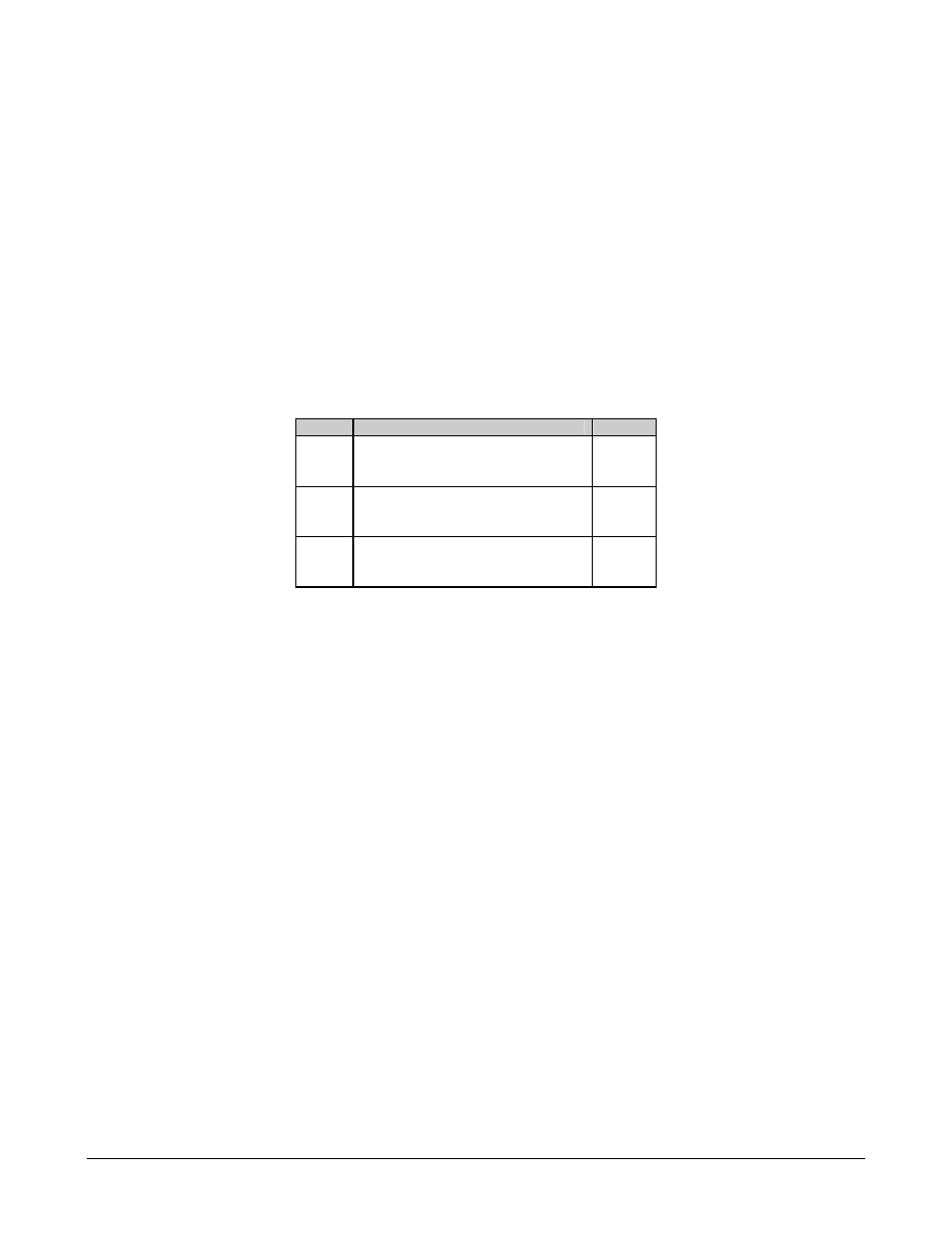
Table 4-3. Fault Connector and Pinouts (J7)
Pin #
Signal Function
Name
1
Common equipment is not faulted
NO
2
COM
3
Common equipment is faulted
NC
4
Modulator is not faulted
NO
5
COM
6
Modulator is faulted
NC
7
Demodulator is not faulted
NO
8
COM
9
Demodulator is faulted
NC
Note: A connection between the common (COM) and normally open (NO) contacts
indicates no fault.
To obtain a system summary fault, connect all the Form C contacts in parallel.