Channel multiplexer specifications, 3 8-channel multiplexer specifications – Comtech EF Data SDM-300A User Manual
Page 318
SDM-300A Sattellite Modem
Revision 6
8-Channel Multiplexer
MN/SDM300A.IOM
14–4
14.3
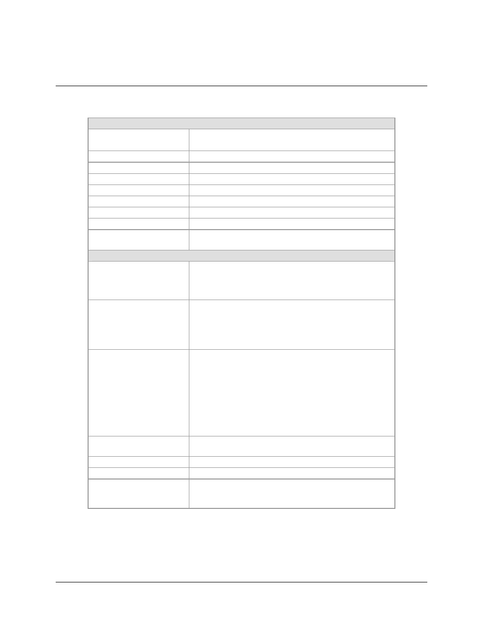
8-Channel Multiplexer Specifications
System Specification
Number of Channels
(Tributaries)
1 to 8, the data rate for each channel is independently configurable.
Tributary Type
Synchronous (clock/data) or Asynchronous (data only).
Tributary Data Interface
EIA-422 or EIA-232-C, selectable per tributary.
Tributary Data Rate
Note: EIA-232-C maximum data rate is 64.0 kbps.
Synchronous
600 bps to 4000 kbps in 100 bps increments.
Asynchronous
600 baud to 64k K-baud in 100 bps increments.
MUX Overhead
1.3 kbps, fixed.
MUX Technique
Data Interleaved Time Division.
Aggregate Data Rate
4001.3 kbps maximum, the aggregate data rate is the sum of all
tributary data rates plus the multiplex overhead.
MUX System Specification
Tributary Data Interface
(Synchronous Mode)
The MUX supports a synchronous data interface for each tributary.
The tributary data interfaces use DCE conventions with data (send
data) sourced by external equipment and clock (send timing) sourced
by the MUX.
Tributary Clock Output
(Synchronous Mode)
50% duty cycle
± 10%, clock (send timing) is phase locked to the
aggregate clock supplied by the modem. Clock stability is based on
the reference source. The clock accuracy will nominally be
10E-5 when using the modem SCT clock. Higher stability can be
obtained by using the modem External Reference input.
Tributary Data Interface
(Asynchronous Mode)
The MUX supports an asynchronous data interface for each tributary.
The tributary data interfaces use DCE conventions with data (send
data) sourced by external equipment. The MUX samples the input
data and passes it across the communications channel. All data
formatting and framing is preserved, including start/stop bits and parity.
Note: CTS (clear to send) flow control is employed to prevent loss of
data caused by clock differences between the asynchronous source
and the synchronous satellite channel.
Receive Channel Pass Through
The MUX provides an output path for the received clock/data from the
SDM-300A modem.
Interface Connector
96-pin female DIN connector (includes all tributary interfaces).
Interface I/O Card (PC/6029)
96-pin male DIN to 100-pin subminiature D conversion PC card.
Breakout Panel (UB-54)
Optional 1 RU breakout panel converts 100-pin D interface to eight 15-
pin D separate tributary interfaces and one 15-pin D connector for
auxiliary circuits.