Data i/o connector (j8) removal, 1 data i/o connector (j8) removal – Comtech EF Data SDM-300A User Manual
Page 73
SDM-300A Satellite Modem
Revision 6
Installation/Upgrades
MN/SDM300A.IOM
3–17
3.7 Data I/O Interface Connector (J8) Removal/Installation
Note: The following procedures outline the removal and installation of the Data I/O connector
(J8). These procedures are written with the assumption that the same configured connector will
be reinstalled. However, the operator does have an option to install a different configured
connector. Refer to Table 3-1 for a matrix explaining connector options.
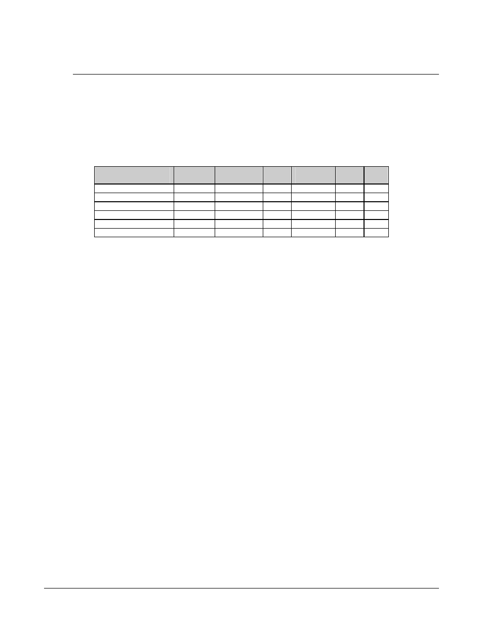
Table 3-1.Connector (J8) Matrix
Modem
Configuration
RS-232
RS-422/
RS-449
V.35
G.703
Flex
Mux
Mux
25-pin Connector
X
X
X
34-pin Connector
X
37-pin
Connector X
50-pin
Connector X
X X X X
100-pin D Connector
X
15-pin/ BNC
X
3.7.1 Data I/O Connector (J8) Removal
1. (For Ribbon-Configured Connector PL/6031.) Remove Data I/O connector (J8)
(Figure 3-5) as follows:
a. Remove four screws securing the rear panel to the chassis.
b. Pull out rear panel to gain access to disconnect connector (J8).
c. Disconnect connector (J8) from the PCB.
d. Remove the four screws securing connector (J8) to the rear panel.
e. Remove the connector (J8).
2. (For Part No. PL/5509-1.) Remove 50-pin Data I/O connector (J8) as follows:
a. Remove the four screws securing the connector (J8) to the rear panel.
b. Establish a grip on connector (J8) and pull backwards until separation of the
connectors is obtained.
c. Remove connector (J8).