Refer to figure 1-1for a system block diagram – Comtech EF Data SDM-300A User Manual
Page 28
SDM-300A Satellite Modem
Revision 6
Introduction
MN/SDM300A.IOM
1–2
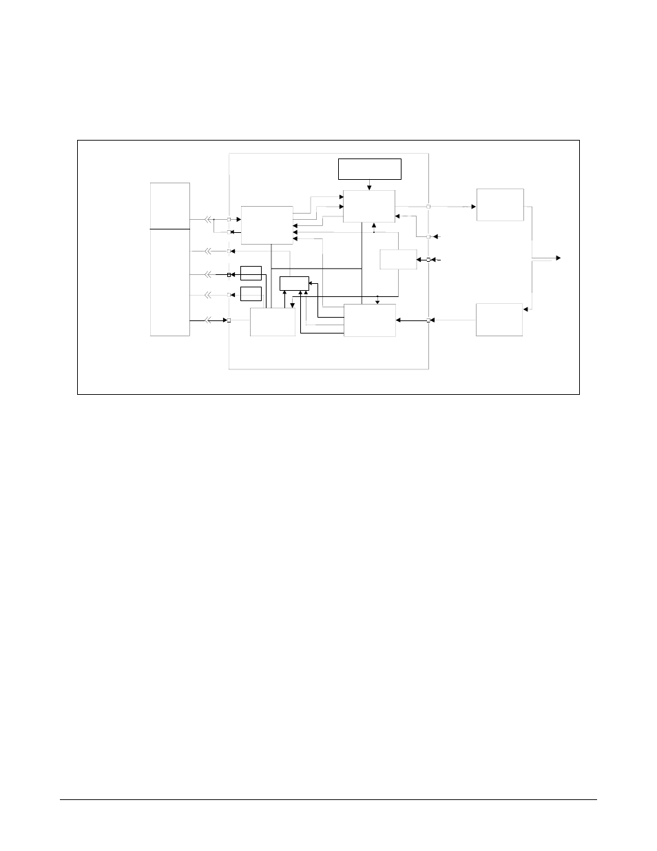
Refer to Figure 1-1for a system block diagram.
M&C
AUX
CIRCUITS
SAT CLK
FAULT
RELAYS
ALARM
RELAYS
+5 TO -20 DBM OPTION
SDM-300A
SATELLITE
MODEM
BOP
CUSTOMER
DATA I\O
AUX 1
TTL FAULTS
FAULT
FORM C
CONTACTS
ALARMS
FORM C
CONTACTS
REMOTE
SERIAL
INTERFACE
J8
J8
J9
J7
J10
J6
INTERFACE
DATA
I/Q
AGC
DEMOD/
DECODER
2x10 REFERENCE
2x10 REF (OPT)
DATA
CLK
SCT
ENCODER/
MODULATOR
POWER
SUPPLY
RECEIVE
RF
EQUIPMENT
50 TO 180 MHZ
-30 TO -55 DBM
90 TO 264 VAC,
47 TO 63 HZ
50 TO 180 MHZ
-5 TO -30 DBM
CP3 EXT REF
(OPTION)
IF INPUT
CP2
ANTENNA
IF OUTPUT
CP 1
TRANSMIT
RF
EQUIPMENT
-5
-7
1
(Optional)
x
x
x
x
x
x
x
Figure 1-1. Block Diagram
Notes:
1. The UB-530 universal breakout panel (BOP) is an option for breaking out the V.35,
G.703, RS-232, or RS-422 signals from the 50-pin data I/O connector.
2. When the modem is equipped with a 50-pin data I/O connector, the use of the BOP is
required to interface the customer data connector to the modem.
3. Contact Comtech EF Data Customer Support department for information concerning
universal breakout panels.