Figure 17. mode 2 interrupt response mode – Zilog Z08470 User Manual
Page 32
Architectural Overview
UM008007-0715
20
Z80 CPU
User Manual
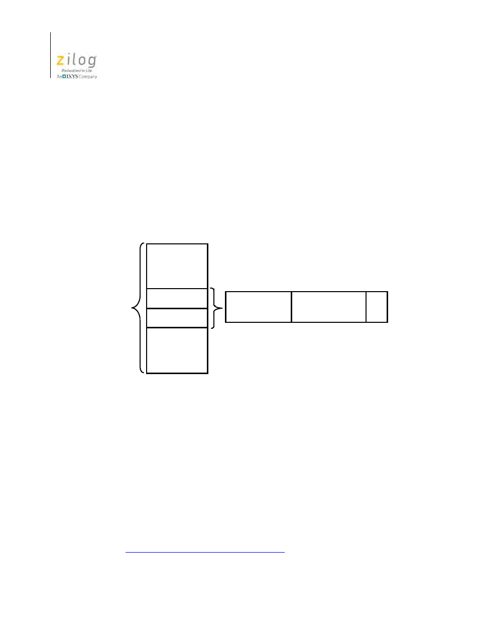
In Mode 2, the programmer maintains a table of 16-bit starting addresses for every inter-
rupt service routine. This table can be located anywhere in memory. When an interrupt is
accepted, a 16-bit pointer must be formed to obtain the required interrupt service routine
starting address from the table. The upper eight bits of this pointer is formed from the con-
tents of the I Register. The I register must be loaded with the applicable value by the pro-
grammer, such as LD I, A. A CPU reset clears the I Register so that it is initialized to 0.
The lower eight bits of the pointer must be supplied by the interrupting device. Only seven
bits are required from the interrupting device, because the least-significant bit must be a 0.
This process is required, because the pointer must receive two adjacent bytes to form a
complete 16-bit service routine starting address; addresses must always start in even loca-
tions.
The first byte in the table is the least-significant (low-order portion of the address). The
programmer must complete the table with the correct addresses before any interrupts are
accepted.
The programmer can change the table by storing it in read/write memory, which also
allows individual peripherals to be serviced by different service routines.
When the interrupting device supplies the lower portion of the pointer, the CPU automati-
cally pushes the program counter onto the stack, obtains the starting address from the
table, and performs a jump to this address. This mode of response requires 19 clock peri-
ods to complete (seven to fetch the lower eight bits from the interrupting device, six to
save the program counter, and six to obtain the jump address).
The Z80 peripheral devices include a daisy-chain priority interrupt structure that automat-
ically supplies the programmed vector to the CPU during interrupt acknowledge. Refer to
the
for more complete information.
Figure 17. Mode 2 Interrupt Response Mode
Starting Address
Pointed to by:
I Register
Contents
Seven Bits From
Peripheral
0
Low Order
High Order
Interrupt
Service
Routine
Starting
Address
Table